


en
Installation and electrical connection
16
WILO SE 2019-02
WARNING
Separation of pressure hose!
Separation or movement of the pressure hose can
lead to (serious) injuries. Securely attach the pressure
hose to the outlet! Prevent buckling of the pressure
hose.
NOTICE
Pumping problems due to water level being
too low
The hydraulics are self-venting. Smaller air cushions
are resorbed during pumping. If the fluid is lowered
too much, separation of the volume flow may occur.
The minimum permissible water level must reach the
upper edge of the hydraulics housing!
For portable installation, the pump is equipped with a pump sup-
port foot. The pump support foot ensures minimum ground
clearance in the suction area and enables secure footing if placed
on a solid bearing surface. In this installation type, the pump can
be installed anywhere in the operating space/installation site. A
hard base must be used at the installation location to prevent
sinking in case of soft bearing surfaces. A pressure hose is con-
nected on the pressure side.
CAUTION! If the motor emerges during operation, observe the
operating mode for non-immersed operation (S2-15, S3
10 %*)!
* Operating mode S3 25 % is permitted if the necessary motor
cooling is guaranteed before the motor is switched on again! To
ensure the required cooling, the motor must be completely im-
mersed for at least 1 min.
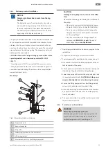
Work steps
1
2
3
4
5
S1
S2, S3
6
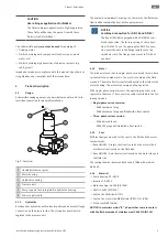
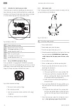
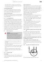
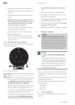
Fig. 7:
Wet well installation, portable
1
Pump with integrated pump support foot
2
Pipe elbow with hose connection or Storz pipe coupling
3
Storz hose coupling
4
Pressure hose
5
Attachment point
6
Lifting equipment
CAUTION
Damage to the pump due to incorrect install-
ation
Observe the following points during the installation
of the pump:
• Observe the max. permissible tightening torque:
15 Nm (11 ft·lb) (V05) or 25 Nm (18 ft·lb) (V06)
• Do not insert an additional gasket between the
flange and the accessories! A gasket is mounted
on the pump flange!
• Only use accessories with a flange shape in ac-
cordance with
EN 1092-2, type A.
The use of
other flange shapes
is not permitted!
‡
Pressure connection prepared: Pipe elbow with hose
connection or pipe elbow with Storz coupling mounted.
1. Use a shackle to attach the lifting equipment to the at-
tachment point of the pump.
2. Lift the pump and lower it at the intended location
(chamber, pit).
3. Place the pump on a solid bearing surface.
CAU-
TION! Sinking must be prevented!
4. Lay the pressure hose and fasten it to a certain point
(e.g. drainage).
DANGER! Separation or movement of
the pressure hose can lead to (serious) injuries! Se-
curely attach the pressure hose to the outlet.
5. Lay the power supply cable properly.
CAUTION! Do not
damage the power supply cable!
▶ The pump is installed, the qualified electrician can make
the electrical connection.
6.4.6
Level control
With a level control device, the current fill levels are determined
and the pump is switched on and off automatically depending on
the fill levels. Fill levels are recorded by using different sensor
types (float switches, pressure and ultrasound measurements or
electrodes). The following must be observed when using a level
control device:
ƒ
Float switches can move freely!
ƒ
The water level must
not fall below
the minimum permissible!
ƒ
The maximum switching frequency
must not be exceeded
!