


en
20
Installation and operating instructions • Wilo-Rexa FIT-S • Ed.01/2022-03
•
Mechanical screw locking device
Always re-apply the screw locking device!
Thread-locking fluid
Medium-strength thread-locking fluid (e.g. Loctite 243) is used for
the liquid screw locking compound. This threadlocker can be
loosened with increased force. If the thread-locking fluid cannot
be loosened, then the compound must be heated to approx. 300 °C
(572 °F). Clean the components thoroughly after dismantling.
Mechanical screw locking device
The mechanical screw locking device consists of two Nord-Lock
wedge lock washers. The screw connection is secured by the
clamping force. The Nord-Lock screw locking device must only be
used on bolts with strength class 10.9 which have been coated
with Geomet.
The use of stainless screws is prohibited!
9.6.2
Replace macerator
A
B
1
2
3
4
4
4
5
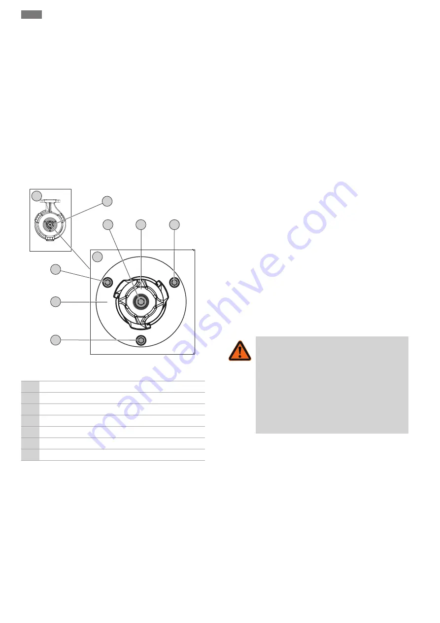
Fig. 9:
Replacing the macerator
A
Overview: View from below
B
Detail view: Macerator with fixation
1
Macerator
2
Cutting plate
3
Cutting head
4
Cutting plate fixation M6
5
Cutting head fixation M8
✓
Wear protective glove!
✓
Pump cleaned and disinfected if necessary.
✓
Hexagon socket with T-handle, sizes 5 and 6.
✓
Torque wrench.
✓
Wedge (width: approx. 10 ... 15 mm) made of hardwood or
plastic to secure the cutting head.
CAUTION! Do not use a metal wedge! A metal wedge can
damage the blades.
✓
Liquid thread-locking fluid, medium strength (e.g. Loctite
243).
1.
Secure the cutting head: Insert wedge between cutting head
and cutting plate.
2.
Loosen and remove fastening screw on cutting head.
3.
Remove wedge.
4.
Pull off cutting head.
WARNING! Cut injury! Do not touch
cutting head on cutting blade!
5.
Fit new cutting head.
6.
Wet fastening screw with thread-locking fluid and screw it
into cutting head. Tighten the fastening screw hand-tight.
7.
Secure the cutting head: Insert wedge between cutting head
and cutting plate.
CAUTION! Tighten fastening screw hand-tight before in-
serting wedge! The wedge can displace the cutting head.
8.
Tighten fastening screw on cutting head to 18.5 Nm (13.5 ft
lb).
9.
Remove wedge.
10. Loosen and unscrew cutting plate fastening screws.
11. Carefully lever out cutting plate with wedge.
12. Remove cutting plate.
WARNING! Cut injury! Do not touch
cutting plate on blade!
13. Insert new cutting plate.
14. Wet cutting plate fastening screws with thread-locking fluid
and screw in.
15. Tighten cutting plate fastening screws crosswise to 7.5 Nm
(5.5 ft lb).
▶
Macerator changed.
NOTICE! Observe drying time! Allow the thread-locking fluid to
dry before using the pump.
10
Faults, causes and remedies
WARNING
Risk of injury from rotating components!
No persons are allowed to be present in the working
area of the pump. There is a risk of injury!
• Demarcate and cordon off the working area.
• If there are no persons in the working area, activ-
ate the pump.
• If persons enter the working area, switch off the
pump immediately.
Fault: Pump does not start
1.
Electricity supply interrupted or short-circuit/earth fault in the
cable or motor winding.
⇒
Have the connection and motor checked by a qualified
electrician and replace if necessary.
2.
Tripping of fuses, of the motor protection switch or the mon-
itoring device
⇒
Have the connection and the monitoring device checked by
a qualified electrician and change it if necessary.
⇒
Have the motor protection switches and fuses installed and
adjusted according to the technical specifications by a
qualified electrician and reset monitoring device.
⇒
Check the impeller to make sure that it runs smoothly,
clean the hydraulics if necessary.


