GWS-090E
Gas-Fired Water Boiler –
Boiler Manual
10
Part Number 550-110-737/1108
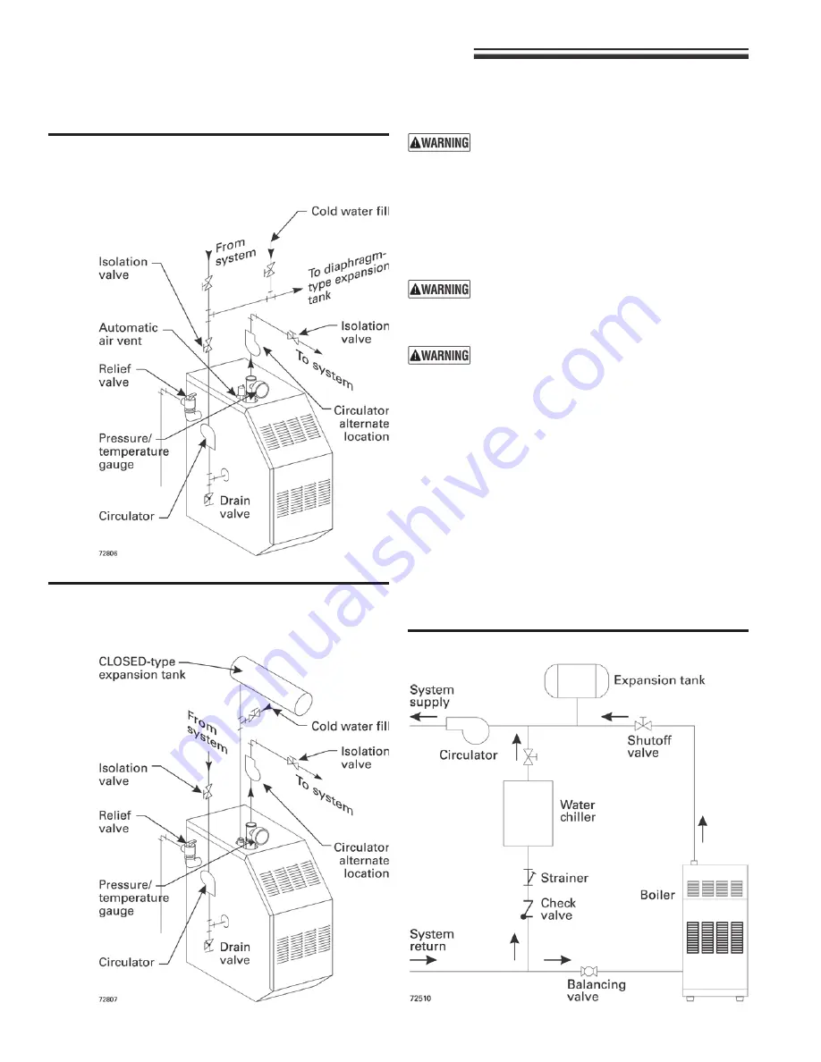
Figure 3
Diaphragm- or bladder-type expansion tank:
Piping to single-zone system using
diaphragm-type or bladder-type expansion
tank. See Table 5, page 9, for piping sizes.
Figure 4
Closed-type expansion tank: Piping to single-
zone system using closed-type expansion
tank. See Table 5, page 9, for piping sizes.
Figure 5
Piping refrigeration systems
3 Install water piping
continued
Water piping — refrigeration systems
Prevent chilled water from entering boiler
Install boiler so that chilled medium is piped in parallel with the
heating boiler. Use appropriate valves to prevent chilled medium
from entering boiler. See Figure 5 for typical installation of balanc-
ing valve and check valve.
Install boiler so that chilled medium is piped in par-
allel with heating boiler. Use appropriate valves to
prevent chilled medium from entering boiler. Consult
I=B=R Installation and Piping Guides.
If boiler is connected to heating coils located in
air handling units where they can be exposed to
refrigerated air, use flow control valves or other au-
tomatic means to prevent gravity circulation during
cooling cycle. Circulation of cold water through the
boiler could result in damage to the heat exchanger,
causing possible severe personal injury, death or
substantial property damage.
If system includes radiant heating circuits, provide
piping and controls to regulate the temperature sup-
plying the radiant circuits. Failure to comply could
result in substantial property damage.
Use Figure 3 or Figure 4 only for systems designed
for return water at least 130 °F. For systems with
low return water temperature possible, such as con-
verted gravity systems and radiant heating systems,
install bypass piping (see page 11) to protect boiler
against condensation. Failure to prevent low return
water temperature to the boiler could cause corro-
sion of the boiler sections or burners, resulting in
severe personal injury, death or substantial property
damage.


