Wilger
Installation and Operation Manual
Wilger Electronic Flow Monitoring System
Page | 12
Overview of the EFM System
Basic Structure
The Electronic Flow Monitoring System can be retro-fitted on an existing liquid
fertilizer or chemical application kit using O-ring seal (ORS) fittings, or added as a
new kit to an existing machine.
One ECU is required per EFM system (and can accommodate up to 196
product outlets/sensors).
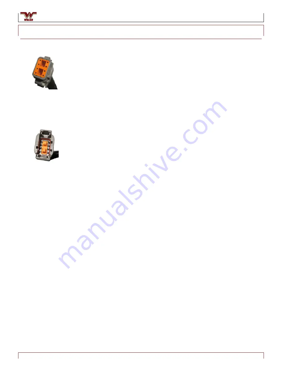
The 8-pin female Deutsch connector from the ECU plugs into the 8-pin male
connector on the harness connected to the first product node (Node 1)
Additional Product Nodes are daisy-chained (using node-to-node extension
cables – if extra harness length is required)
There are two types of product nodes: 4-channel (4CH) and 16-channel
(16CH)
NOTE: Wherever possible, use 16CH nodes. Use 4CH nodes only where four sensors
or less are required
4CH nodes connect to a harness that allows connection to four single-
sensor cables
16CH nodes connect to a product node harness that allows connection
to four quad-sensor cables, which facilitates the use of up to 16 sensors
in total
Each unused product node connection should be capped to protect
connections from possible corrosion.
Sensors are designated by node, cable, and sensor.
Example: Sensor 2B3 is Node 2, Cable B, Sensor 3 (See Figure 21)
The last product harness in the chain requires a node harness terminator.
Figure 19. 8-Pin
Female Connector
Figure 20. 8-Pin Male
Connector


