background image

WIL-11111-E-03  

7


WILDEN PUMP & ENGINEERING, LLC

H O W   T O   U S E   T H I S   E M S ™   C U R V E

SETTING 4 PERFORMANCE CURVE

EMS CURVE

8.2  

GPM

Example data point =  

Example data point =  

Figure 1

Figure 2

0.58
0.48

fl ow multiplier

air multiplier

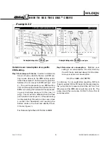
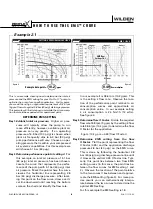
This is an example showing how to determine fl ow rate and 
air consumption for your Pro-Flo X™ pump using the Effi cien-
cy Management System (EMS) curve and the performance 
curve. For this example we will be using 4.1 bar (60 psig) inlet 
air pressure and 2.8 bar (40 psig) discharge pressure and EMS 
setting 2.

Step 1:

  Identifying performance at setting 4.  

Locate 

the curve that represents the fl ow rate of the 
pump with 4.1 bar (60 psig) air inlet pressure.  
Mark the point where this curve crosses the 
horizontal line representing 2.8 bar (40 psig) 
discharge pressure. (Figure 1).  After locating 
your performance point on the fl ow  curve, 
draw a vertical line downward until reaching 
the bottom scale on the chart.  Identify the fl ow 
rate (in this case, 8.2 gpm).  Observe location 
of performance point relative to air consump-
tion curves and approximate air consumption 
value (in this case, 9.8 scfm).

Step 2:   

Determining flow and air X Factors. 

Locate 

your discharge pressure (40 psig) on the verti-
cal axis of the EMS curve (Figure 2).  Follow 
along the 2.8 bar (40 psig) horizontal line until 
intersecting both fl ow and air curves for your 
desired EMS setting (in this case, setting 2). 
Mark the points where the EMS curves inter-
sect the horizontal discharge pressure line. 
After locating your EMS points on the EMS 

curve, draw vertical lines downward until 
reaching the bottom scale on the chart.  This 
identifi es the fl ow X Factor (in this case, 0.58) 
and air X Factor (in this case, 0.48).

Step 3:

  Calculating performance for specific EMS 

setting. 

Multiply the fl 

ow rate (8.2 gpm) 

obtained in Step 1 by the fl ow X Factor multi-
plier (0.58) in Step 2 to determine the fl ow rate 
at EMS setting 2.  Multiply the air consump-
tion (9.8 scfm) obtained in Step 1 by the air 
X Factor multiplier (0.48) in Step 2 to deter-
mine the air consumption at EMS setting 2 
(Figure 3). 

Figure 3

The fl ow rate and air consumption at Setting 
2 are found to be 18.2 lpm (4.8 gpm) and 7.9 
Nm

3

/h (4.7 scfm) respectively.

.58
4.8 

gpm

(Flow X Factor setting 2)

(Flow rate for setting 2)

(air consumption for setting 4)

(Air X Factor setting 2)

(air consumption for setting 2)

9.8 

scfm

.48
4.7 

scfm

8.2 

gpm

(fl ow rate for Setting 4)

 Example 1

Summary of Contents for HX400S

Page 1: ...W h e r e I n n o v a t i o n F l o w s www wildenpump com HX400S Advanced Series Metal Pump EOM Engineering Operation Maintenance WIL 11111 E 03 TO REPLACE WIL 11111 E 02 ...

Page 2: ...INGS 4 SECTION 5 PERFORMANCE 5 A HX400S PERFORMANCE Operating Principle 6 TPE Fitted Aluminum 10 TPE Fitted Stainless Steel 11 B SUCTION LIFT CURVE 12 SECTION 6 SUGGESTED INSTALLATION 13 Operation Maintenance 14 Troubleshooting 15 SECTION 7 PUMP DISASSEMBLY 16 HX400S Piston Shaft Orientation 18 Air Valve Center Section Disassembly 19 Submersible Pro Flo X 21 Reassembly Hints Tips 22 SECTION 8 EXPL...

Page 3: ...in submersible applications Turbo Flo pumps can also be used in submersible applications CAUTION When choosing pump materials be sure to check the temperature limits for all wetted components Example Viton has a maximum limit of 176 7 C 350 F but polypropylene has a maximum limit of only 79 C 175 F CAUTION Maximum temperature limits are based upon mechanical stress only Certain chemicals will sign...

Page 4: ...ALUMINUM S STAINLESS STEEL VALVE SEAT O RING TF PTFE white dot HX400S METAL 38 mm 1 1 2 Pump Maximum Flow Rate 235 LPM 62 GPM LEGEND MATERIAL CODES SPECIALTY CODES MODEL VALVE SEAT SPECIALTY O RING CODE if applicable VALVE SEAT VALVE BALL DIAPHRAGM AIR VALVE CENTER BLOCK AIR CHAMBER WETTED PARTS OUTER PISTON XHX400S XXXXX XXX XX XXX XXXX NOTE Most elastomeric materials use colored dots for identif...

Page 5: ...oped in the liquid chamber and manifold of the pump These same hydraulic forces lift the discharge valve ball off of its seat forcing fluid to flow through the pump discharge The pres sure on diaphragm A creates a force on the shaft that is combined with the pressure from diaphragm B This total load is transferred to the liquid creating a liquid pressure that is two times greater than the supplied...

Page 6: ...7 5 0 G 323 12 7 H 48 1 9 J 132 5 2 K 310 12 2 L 518 20 4 M 241 9 5 N 203 8 0 P 152 6 0 R 170 6 7 S 10 0 4 DIN mm ANSI inch T 150 DIA 6 1 DIA U 110 DIA 4 5 DIA V 18 DIA 0 9 DIA REV A REV B DIMENSIONS DIMENSIONS ITEM METRIC mm STANDARD inch A 384 15 1 B 89 3 5 C 277 10 9 D 528 20 8 E 279 11 0 F 48 1 9 G 132 5 2 H 310 12 2 J 508 20 0 K 84 3 3 L 274 10 8 M 224 8 8 N 178 7 0 P 203 8 0 R 10 0 4 DIN mm ...

Page 7: ...WIL 11111 E 03 5 WILDEN PUMP ENGINEERING LLC H X 4 00 S A D VA N C E D T M P E R FO R M A N C E H X 400S ...

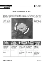
Page 8: ...gher performance lower operational costs and flexibility that exceeds previous industry standards Pro Flo XTM Operating Principal Turning the dial changes the relationship between air inlet and exhaust porting Each dial setting represents an entirely different flow curve Pro Flo X pumps are shipped from the factory on setting 4 which is the highest flow rate setting possible Moving the dial from sett...

Page 9: ... this case 9 8 scfm Step 2 Determining flow and air X Factors Locate your discharge pressure 40 psig on the verti cal axis of the EMS curve Figure 2 Follow along the 2 8 bar 40 psig horizontal line until intersecting both flow and air curves for your desired EMS setting in this case setting 2 Mark the points where the EMS curves inter sect the horizontal discharge pressure line After locating your ...

Page 10: ...40 psig discharge pressure After locat ing this point on the flow curve draw a verti cal line downward until reaching the bottom scale on the chart and identify the flow rate In our example it is 38 6 lpm 10 2 gpm This is the setting 4 flow rate Observe the loca tion of the performance point relative to air consumption curves and approximate air consumption value In our example setting 4 air consumpt...

Page 11: ...different than the flow point plotted in example 2 1 After estimating or interpolating this point on the curve draw a vertical line downward until reaching the bottom scale on the chart and identify the air X Factor figure 7 Step 2 Determine air consumption Multiply your setting 4 air consumption 14 scfm value by the air X Factor obtained above 0 40 to deter mine your actual air consumption In summa...

Page 12: ...g curves for operation at intermediate EMS settings 100 is TECHNICAL DATA Height 605 mm 23 8 Width 345 mm 13 6 Depth 310 mm 12 2 Est Ship Weight Aluminum 27 kg 60 lbs Air Inlet 19 mm 3 4 Inlet 38 mm 1 1 2 Outlet 38 mm 1 1 2 Suction Lift 2 5 m Dry 8 2 8 6 m Wet 28 2 Disp Per Stroke 0 5 l 0 12 gal 1 Max Flow Rate 235 lpm 62 gpm Max Size Solids 8 0 mm 5 16 1 Displacement per stroke was calculated at ...

Page 13: ...peration at intermediate EMS settings TECHNICAL DATA Height 528 mm 20 8 Width 384 mm 15 1 Depth 310 mm 12 2 Est Ship Weight Stainless Steel 37 kg 82 lb Air Inlet 19 mm 3 4 Inlet 38 mm 1 1 2 Outlet 38 mm 1 1 2 Suction Lift 2 3 m Dry 8 2 8 6 m Wet 28 2 Disp Per Stroke 0 4 l 0 11 gal 1 Max Flow Rate 199 lpm 53 gpm Max Size Solids 4 8 mm 3 16 1 Displacement per stroke was calculated at 4 8 bar 70 psig...

Page 14: ... 1 4 2 1 2 8 3 4 4 1 4 8 5 5 6 2 6 9 PSIG BAR Aluminum Wetted Path Stainless Steel Wetted Path Suction lift curves are calibrated for pumps operating at 305 m 1 000 above sea level This chart is meant to be a guide only There are many variables which can affect your pump s operat ing characteristics The number of intake and discharge elbows viscosity of pumping fluid elevation atmospheric pressure...

Page 15: ...s of prime troubles will be eliminated In addition pump efficiency can be adversely affected if proper atten tion is not given to site location PIPING Final determination of the pump site should not be made until the piping challenges of each possible location have been evalu ated The impact of current and future installations should be consid ered ahead of time to make sure that inadvertent restr...

Page 16: ... schedules may be different for every pump Frequency of use line pressure viscosity and abrasiveness of process fluid all affect the parts life of a Wilden pump Periodic inspections have been found to offer the best means for prevent ing unscheduled pump downtime Personnel familiar with the pump s construction operation and service should be informed of any abnormalities that are detected during o...

Page 17: ...unable to shift 7 Remove plug from pilot spool exhaust PUMP RUNS BUT LITTLE OR NO PRODUCT FLOWS 1 Check for pump cavitation slow pump speed down to allow thick material to flow into liquid chambers 2 Verify that vacuum required to lift liquid is not greater than the vapor pressure of the material being pumped cavitation 3 Check for sticking ball check valves If material being pumped is not compati...

Page 18: ...rom each liquid chamber to its corre sponding air chamber This line will assist in proper realignment during reassembly Step 2 Using a 3 4 wrench loosen the discharge manifold from the liquid chambers Step 3 Remove the discharge manifold to expose the top left valve ball NOTE the HX400S pump does not use valve balls in the amplification chamber Step 4 Remove the discharge valve ball valve seat and...

Page 19: ...n adjustable wrench remove the diaphragm assembly from diaphragm shaft by turning counter clockwise Step 11 After loosening and removing the diaphragm assembly remove opposite liquid chamber Step 12 After removing the opposite liquid cham ber the remaining diaphragm assembly and diaphragm shaft can be easily removed Step 13 To remove diaphragm assembly from shaft secure shaft with soft jaws a vise...

Page 20: ...bling the HX400S pump the outer piston with the air passageway has to be positioned on the same side as the amplification chamber If it is not reassem bled correctly the pump will not operate and process fluid will enter the air distribu tion system through the air passageway located at the shaft lug AIR PASSAGEWAY AIR PASSAGEWAY AIR PASSAGEWAY This same air passageway continues through the diaphr...

Page 21: ...ffler plate and air valve bolts from air valve assembly Lift away air valve assembly and remove air valve gasket and muffler plate gasket for inspection Replace if necessary Step 3 Remove air valve end cap to expose air valve spool by simply lifting up on end cap once air valve bolts are removed NOTE Pro Flo X air valve incorporates an end cap at both ends of the air valve Step 4 Remove the air va...

Page 22: ... spool from pilot spool sleeve and inspect for nicks gouges and wear Replace pilot sleeve or outer sleeve O rings if necessary During re assembly never insert the pilot spool into the sleeve with the notched end first this end incorporates the urethane O ring and will be damaged as it slides over the ports cut in the sleeve NOTE Seals should not be removed from pilot spool Seals are not sold separ...

Page 23: ...e plug 00 7010 08 into the pilot spool bleed port located at the front of the center block Step 2 Next install an optional submersible air valve gasket 04 2621 52 The submersible air valve gasket can be purchased as a spare part or included with the purchase of a new Pro Flo X pump Non Submersible Submersible ...

Page 24: ...h a new seal in hand place the two legs of the needle nose pliers inside the seal ring See Figure A Open the pliers as wide as the seal diameter will allow then with two fingers pull down on the top portion of the seal to form kidney bean shape See Figure B Lightly clamp the pliers together to hold the seal into the kid ney shape Be sure to pull the seal into as tight of a kidney shape as possible ...

Page 25: ...N O T E S ...

Page 26: ...WILDEN PUMP ENGINEERING LLC 24 WIL 11111 E 03 HX400S ALUMINUM T P E F I T T E D E X P L O D E D V I E W S e c t i o n 8 E X P L O D E D V I E W PA R T S L I S T I N G ...

Page 27: ...50 SelfTapping 1 04 6345 08 19 Muffler 1 15 3510 99R WETTED PATH COMPONENTS 20 Liquid Chamber 2 04 4980 01 21 Washer 3 8 16 15 6740 08 50 22 Screw HHC 3 8 16 x 1 1 4 16 04 6140 08 23 Discharge Elbow 2 04 5250 01 24 Washer 1 2 40 04 6730 08 25 Screw HHC 1 2 13 x 1 1 2 8 04 6180 08 26 Screw HHC 1 2 13 x 2 16 04 6210 08 27 Hex Nut 1 2 13 16 15 6420 08 28 Tee Section ANSI XHX400S 2 04 5181 01 Tee Sectio...

Page 28: ...WILDEN PUMP ENGINEERING LLC 26 WIL 11111 E 03 HX400S STAINLESS STEEL T P E F I T T E D E X P L O D E D V I E W E X P L O D E D V I E W PA R T S L I S T I N G ...

Page 29: ...ew 10 32 X 50 SelfTapping 1 04 6345 08 04 6345 08 19 Muffler 1 15 3510 99R 15 3510 99R WETTED PATH COMPONENTS 20 Liquid Chamber Bolted 2 04 5000 03 42 04 5000 03 42 21 Disc SpringWasher 5 16 32 08 6810 03 42 08 6810 03 42 22 Screw HHC 5 16 18 x 1 3 8 16 08 6100 03 08 6100 03 23 Hex Nut 5 16 18 32 08 6400 03 08 6400 03 24 Discharge Manifold ANSI 1 04 5032 03 04 5032 03 Discharge Manifold DIN 1 04 502...

Page 30: ...N O T E S ...
Page 31: ... manufacture whichever comes first Failure due to normal wear misapplication or abuse is of course excluded from this warranty Since the use of Wilden pumps and parts is beyond our control we cannot guarantee the suitability of any pump or part for a particular application and Wilden Pump and Engineering LLC shall not be liable for any consequential damage or expense arising from the use or misuse ...

Page 32: ...AR INTERNAL GEAR PUMPS envirogearpump com FLUID DYNAMICS POLYMER BLENDING SYSTEMS neptune1 com GRISWOLD CENTRIFUGAL PUMPS griswoldpump com MAAG GROUP GEAR PUMPS PELLETIZING FILTRATION SYSTEMS maag com MOUVEX ECCENTRIC DISC PUMPS VANE PUMPS COMPRESSORS mouvex com NEPTUNE DIAPHRAGM METERING PUMPS POLYMER SYSTEMS MIXERS neptune1 com QUATTROFLOW 4 PISTON DIAPHRAGM quattroflow com REDSCREW SCREW PUMPS r...

Reviews: