background image

white

green

brown

white

green

brown

User Manual 5.12 (2019-09) 11

Subject to change

Series FR92K

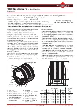
Assembly:


The connection cable must 

be routed towards the 

outside on the operation 

side (release element side) 

of the fire damper. It must 

not obstruct the cover level 

or the damper blade.

FR90 fire dampers 

in short lengths

Optional 

accessories, installation, maintenance-free, functional test and servicing

Installation

 FR90 fire dampers, series FR92K, must be installed 

according to the instructions in this user manual. 


Structural requirements for walls, ceilings, ventilation 

ducts etc. must be met by the customer.

  The  technical  regulations  and  national  statutory 

regulations must be observed during installation. 


In Germany, this means the “Technical Building 

Regulations” (VV TB) and the “Guideline on Fire 

Protection Requirements Pertaining to Ventilation 

Systems” (Lüftungsanlagenrichtlinie - LüAR).

 FR90 fire dampers, series FR92K, may be connected 

to  ventilation  ducts  made  of  non-combustible  and 

combustible  materials.  Thermal  expansion  in  case 

of  fire  must  not  subject  the  fire  dampers  to  notable 

forces. Compensatory measures must be provided as 

required. In general, the compensation is achieved by 

routing ducts appropriately.


FR90 fire dampers, series FR92K

  •

  Do not need spacing to separate from combustible 

materials.

  •

 Are suitable for all installation positions.

  •

  Can be installed with a minimum distance of 15 mm,


also in metal stud walls.


Electric wiring

 must be performed on site.

Maintenance-free

 FR90 fire dampers, series FR92K, are maintenance-

free as a result of the full enclosure, corrosion-resistant 

materials and precise manufacture.

  The stainless steel operation mechanics are situated in 

an enclosure, not in the air flow. There is no requirement 

for recurrent cleaning and lubrication.

  Damper  blades  are  break-proof.  Seals  and  other 

materials are engineered to be durable.

Functional testing and servicing

 Fire  dampers  must  be  maintained  by  the  owner. 

Functional  checks  should  be  performed  periodically 

and depend largely on operation of the system. The 

regulations must be adhered to.

 Repairs or service work are required in the event of 

malfunctions. Original spare parts must be used.

 Cleaning  work  required  in  ventilation  systems  for 

hygiene reasons must be performed in an operation-

dependent manner, and also includes the fire dampers.

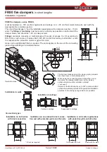
Limit  switches

  for  signalling  the  damper  position 

CLOSED can be retrofitted and must be installed on site.

Pack: 

Limit switch, cable tie, end nipple for casing wall 

installation, strain relief, installation instructions.

Electrical connection:

Limit switch is not actuated

Limit switch is actuated

Connection cable colour coding

Operating instructions


for FR92K series FR90 fire dampers available for download at www.wildeboer.eu

Summary of Contents for FR90

Page 1: ...d walls Sizes DN 100 mm to DN 315 mm Fire classification EI 30 60 90 120 ve ho i o S Options Protective grille DN 100 to DN 200 for air transfer applications Non return valves DN 160 and DN 200 Limit...

Page 2: ...esistant damper blade with elastomer lip seal Leak tightness class 3 according to EN 1751 Large free cross section enables Maximum volume flows Minimum pressure loss Minimum sound levels Release eleme...

Page 3: ...DN 100 to DN 200 see pages 2 and 8 to 10 Connecting piece AR with non return valve and trav erse for screw fastening the protective grille SG1 or SG2 on the non operation side L2 Sizes DN 160 to DN 2...

Page 4: ...ers series FR92K can be used at a velocity of up to 15 m s in the inflow cross section AA and up to 2500 Pa operating pressure FR90 fire dampers in short lengths Dimensioning 1 pressure drop sound pow...

Page 5: ...User Manual 5 12 2019 09 5 Subject to change Series FR92K FR90 fire dampers in short lengths Dimensioning 2 pressure drop sound power level with protective grilles connection Installation on one side...

Page 6: ...metal stud walls each with the appropriate fire resistance period The circumferential gap s and the installation gaps between fire dampers must be 15 mm wide The fillings or mortaring must be made as...

Page 7: ...fire walls shaft walls shafts or ducts Required minimum thicknesses for installation of the fire damper W D mm Fire resistance period in minutes 30 60 90 120 Rigid walls 100 Rigid ceilings 100 The met...

Page 8: ...rten on site to 60 mm 235 75 Shorten on site to 60 mm 75 100 L2 L1 Installation opening DN 50 W D1 SG1 SG1 AS AS The damper blade can be installed with the axis in the vertical or horizontal position...

Page 9: ...non return valve must be installed with vertical axes All longitudinal pipe cuts are then horizontal A maximum deviation of 5 is permissible Install connecting piece AR with the non return valve on no...

Page 10: ...flow Sizes DN 100 DN 125 DN 160 DN 200 D1 mm 125 145 185 235 Connecting pieces AS made of galvanized sheet steel are for fitting onto the fire damper plug connections fitted with lip seals Traverses a...

Page 11: ...ate from combustible materials Are suitable for all installation positions Can be installed with a minimum distance of 15 mm also in metal stud walls Electric wiring must be performed on site Maintena...

Page 12: ...00 125 160 200 250 315 10 12 16 20 25 31 pcs limit switch ES FR92K ES pcs connecting piece AS without non return valve FR92K AS DN size 100 125 160 200 10 12 16 20 55 5 5 5 75 7 7 7 7 100 10 10 10 10...

Page 13: ...anized sheet steel on one side on both sides and with a traverse for screw fastening a protective grille With connecting piece made of galvanized sheet steel on one side with metal non return valve an...

Page 14: ...WEENER EMS Utrecht K LN Factory Administration Telephone 49 0 4951 950 0 Fax 49 0 4951 950 27120 E mail info wildeboer de Internet www wildeboer eu Utrecht office Telephone 31 30 767 0150 E mail info...

Reviews: