www.wika.com
2
3. VALVES IDENTIFICATIONS
We recommend checking, before commissioning, that
the conditions of use are in compliance with the design
specification of the valve.
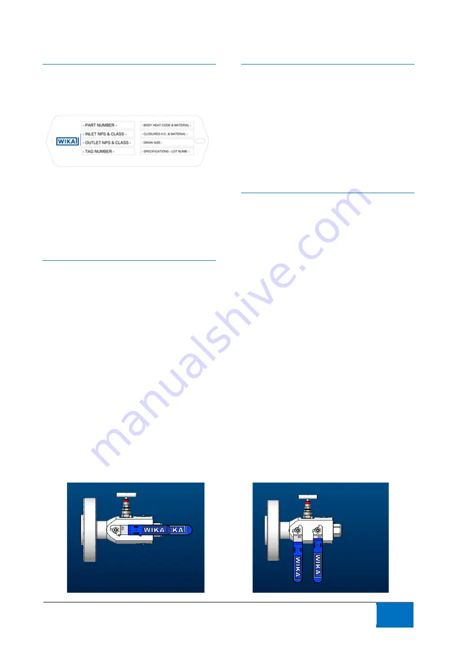
Valves features can be read on the tag plate attached to
the
valve
body.
Valves identifications included:
-
Part number
-
Inlet & outlet dimensions and class
-
Tag number
-
Heat codes
-
Drain size
-
Specification applied
-
Lot number
4. HANDLING AND STORAGE
Valves shall be stored in a dry and clean place.
Condensation shall be avoided through suitable warming
and ventilation system.
Prior to storage, inspect the valve for shipping damage.
Keep all protective packaging, flange covers and end
caps attached to the valves during storage.
During storage valves shall be kept in close position to
avoid introduction of foreign bodies.
Carbon steel valves have an oil finish to retard rusting
during storage: it is not a substitute for paint or other
means of protective coating to be applied to the valve
once installed.
Stainless steel valves have their natural finish and do not
require additional protection once installed.
Valves shall be handled by use of lifting lugs or other
suitable lifting devices.
It is suggested not to lift the valves by means of valve
handles.
5. OPERATING INSTRUCTIONS
On manual operated valves, the valve operation is done
by turning the valve handle 90° clockwise to open
(handle is parallel to flow line), and 90° counter clockwise
to close (handle is perpendicular to flow line).
The bleed line should be in closed position while flow line
is in open position, and open when flow line is in closed
position. To open the bleed valve, turn counter clockwise
the T bar up to the limit. To close turn clockwise the T
bar.
Before starting to open the bleed valve is suggested to
remove the plug on the bleed line if any.
6. INSTALLATION
Monoblock instrumentation valves are potentially
bidirectional so they do not have preferential flow
direction.
Just before installation unpack the valve and remove the
flange and closure fitting protection: ensure that no
packing material are in the flow passages or attached to
the body.
Check for damage and internal and external corrosion if
any.
Inspect the functionality of the valve opening and close
few times both flow line and bleed line.
Balls shall be in open position during the installation to
avoid their damage.
Make sure that flange faces and threads ends are free
from damage, rust, dust or foreign bodies.
It is suggest to clean flanged pipeline connection before
the installation of the valve (flush with nitrogen or other
inert gas) and to remove foreign bodies or dirt from the
internal of the pipes.
If welding operations are required ensure that
temperature do not exceed 150°C. We recommend to
keep the ball in open position.
Gaskets, flange bolts, bolts torque value, sealants,
adapters and tube fittings are responsibility of the
customer.
VALVE OPEN
VALVE CLOSED


