background image

EN

40202780.03 07/2017 EN/DE

22

WIKA operating instructions model A2G-50

5. Commissioning, operation

5.7 Zero point setting
5.7.1 Standard
Connect the voltage supply one hour before the zero point setting!

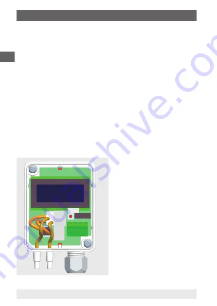
1. Remove both hoses from the pressure connections ⊕ and ⊖.

2. Press the zero button until the red LED switches on.

3. Wait until the LED switches off again and install the hoses to the 

pressure connections again.

4. In normal operation, we recommend that a zero point calibration is 

carried out every 12 months.

5.7.2 Automatic zero point setting (option)

The automatic zero point setting makes the instrument maintenance-

free. The element corrects the zero point from time to time and thus 

prevents a zero-point drift in the piezoresistive sensor element.
During the zero point setting the display and output value remains at the 

last measured value. The automatic zero point setting takes 3 seconds 

and is repeated every 10 minutes.

ZERO

40376281X.01

Summary of Contents for air2guide A2G-50

Page 1: ...EN Operating instructions Betriebsanleitung Differential pressure transmitter model A2G 50 Model A2G 50 ...

Page 2: ...ander Wiegand SE Co KG All rights reserved Alle Rechte vorbehalten WIKA is a registered trademark in various countries WIKA ist eine geschützte Marke in verschiedenen Ländern Prior to starting any work read the operating instructions Keep for later use Vor Beginn aller Arbeiten Betriebsanleitung lesen Zum späteren Gebrauch aufbewahren ...

Page 3: ...onformity can be found online at www wika com 1 General information 4 2 Design and function 5 3 Safety 6 4 Transport packaging and storage 11 5 Commissioning operation 12 6 Modbus version 23 7 Maintenance cleaning and recalibration 27 8 Dismounting return and disposal 28 9 Specifications 31 10 Accessories 33 ...

Page 4: ...nd work instructions are observed Observe the relevant local accident prevention regulations and general safety regulations for the instrument s range of use The operating instructions are part of the product and must be kept in the immediate vicinity of the instrument and readily accessible to skilled personnel at any time Pass the operating instructions on to the next operator or owner of the in...

Page 5: ...del A2G 50 differential pressure transmitter is used for measuring differential pressures of gaseous media in ventilation and air conditioning applications It is based on the piezoresistive measuring principle Electrical analogue output signals for both measurands 0 10 V or 4 20 mA adjustable in the instrument via jumpers or the digital Modbus versions enable the direct connection to control syste...

Page 6: ...ssure transmitter 2 mounting screws 2 duct connectors option 2 x 2 m PVC measuring hose option Cross check scope of delivery with delivery note 3 Safety 3 1 Explanation of symbols WARNING indicates a potentially dangerous situation that can result in serious injury or death if not avoided 40405589 02 2 Design and function 3 Safety ...

Page 7: ... surfaces or liquids if not avoided Information points out useful tips recommendations and information for efficient and trouble free operation 3 2 Intended use This differential pressure transmitter is used for Monitoring the differential pressure of air and other non inflammable and non aggressive gases Monitoring of air filters blowers in ventilation ducts Control of air and fire shutters and f...

Page 8: ...ardous situations and injuries Refrain from unauthorised modifications to the instrument Do not use the instrument within hazardous areas Do not use the instrument with abrasive or viscous media Any use beyond or different to the intended use is considered as improper use Do not use this instrument in safety or emergency stop devices 3 4 Responsibility of the operator The instrument is used in the...

Page 9: ... have the qualifications described below Skilled electrical personnel Skilled electrical personnel are understood to be personnel who based on their technical training know how and experience as well as their knowledge of country specific regulations current standards and directives are capable of carrying out work on electrical systems and independently recognising and avoiding potential hazards ...

Page 10: ...250 Pa Output 0 10 V 4 20 mA Supply DC 24 V AC 24 V 10 1 W Made in EU E Nr 66209848 3 6 Labelling safety marks Product label example 3 Safety Model Measuring range Output signal Power supply Serial number Before mounting and commissioning the instrument ensure you read the operating instructions ...

Page 11: ...instrument is transported from a cold into a warm environment the formation of condensation may result in instrument malfunction Before putting it back into operation wait for the instrument temperature and the room temperature to equalise 4 2 Packaging and storage Do not remove packaging until just before mounting Keep the packaging as it will provide optimum protection during transport e g chang...

Page 12: ...to property and the environment caused by hazardous media Upon contact with hazardous media e g oxygen acetylene flammable or toxic substances harmful media e g corrosive toxic carcinogenic radioactive and also with refrigeration plants and compressors there is a danger of physical injuries and damage to property and the environment Should a failure occur aggressive media with extremely high tempe...

Page 13: ...upply unit e g short circuit from the mains voltage to the output voltage can result in life threatening voltages at the instrument 1 Instrument fixing at the desired mounting location see chapter 5 1 Instrument mounting 2 Opening the instrument cover feeding the connection cable through the cable gland and connecting the wires to the terminal block see chapter 5 2 Electrical mounting 3 The instru...

Page 14: ...e transmitter onto a suitable vertical surface and fix it horizontally with the mounting screws delivered with the instrument 1 Select a mounting location duct wall panel 2 Remove the case cover and use the screw holes as a template 3 Mount with suitable screws 5 Commissioning operation Instrument fixing Instrument orientation ...

Page 15: ...N WIKA operating instructions model A2G 50 40202780 03 07 2017 EN DE 15 5 Commissioning operation 1 2 3 Application related connections Static pressure measurement Filter monitoring Ventilator monitoring ...

Page 16: ...e the A2G 50 with a constant operating voltage 0 2 V and ambient temperature Prevent current voltage spikes from switching the power supply on or off For CE conformity a properly grounded protective cable is required 1 Unscrew the strain relief and feed the cable s through 2 Connect the wires see Connection diagram 3 Tighten down the strain relief Connection diagram Output signal DC 0 10 V V A Pre...

Page 17: ...ing range see chapter 5 5 4 Select the desired response time see chapter 5 6 5 Carry out a zero point setting see chapter 5 7 6 Connect measurement hoses overpressure connection vacuum connection 7 Close the cover The instrument is now ready for operation Pressure P Signal U 100 10 0 V 50 5 0 V 0 0 0 V Time axis t s Pressure P Signal I 100 20 0 mA 50 12 0 mA 0 4 0 mA Time axis t s V A Power supply...

Page 18: ...insert a jumper between both J5 pins see figure Storing the jumper 2 Then press the zero point setting button and the various pressure units Pa kPa inchWC mmWC psi will be shown on the display 3 Remove the jumper from J5 in order to select the desired unit which should be shown on the display Installing the jumpers Dark grey colour indicates the jumper placement No jumper Circuit open Jumper insta...

Page 19: ... 10 2 0 0145 0 0145 2 0 100 0 0 10 0 1 0 0 0 40 0 10 2 0 0 0145 3 0 250 0 0 25 0 2 50 0 1 00 0 25 5 0 0 0363 4 0 500 0 0 50 0 5 00 0 2 00 0 51 0 0 0 0725 5 0 1 000 0 1 00 0 10 0 0 4 00 0 102 0 0 0 1450 6 0 1 500 0 1 50 0 15 0 0 6 00 0 153 0 0 0 21725 7 0 2 000 0 0 20 0 20 0 0 8 00 0 204 0 0 0 2900 8 0 2 500 0 2 50 0 25 0 0 10 00 0 255 0 0 0 3625 Version 2 MB Pressure unit Pa kPa mbar inchWC mmWC p...

Page 20: ...45 4 0 250 0 0 25 0 2 50 0 1 00 0 25 5 0 0 0363 5 25 25 0 025 0 025 0 25 0 25 0 10 0 10 2 6 2 6 0 0036 0 0036 6 50 50 0 05 0 05 0 50 0 50 0 20 0 20 5 1 5 1 0 0073 0 0073 7 100 100 0 1 0 1 1 00 1 00 0 40 0 40 10 2 10 2 0 0145 0 0145 8 250 250 0 25 0 25 2 50 2 50 1 00 1 00 25 50 25 50 0 0363 0 0363 MB measuring range Jumper placement to set the measuring range Range 1 Jumper J1 Jumper J2 Jumper J3 R...

Page 21: ...ponse time defines the time the measuring instrument needs in order to reach 63 of the measured value For unstable pressure conditions select a longer response time Example Selected response time 4 0 seconds Result The output signal reaches a new value in 20 seconds response time 5 In order to change the response time install or remove a jumper in slot J4 Jumper in slot J4 4 0 seconds response tim...

Page 22: ...oses to the pressure connections again 4 In normal operation we recommend that a zero point calibration is carried out every 12 months 5 7 2 Automatic zero point setting option The automatic zero point setting makes the instrument maintenance free The element corrects the zero point from time to time and thus prevents a zero point drift in the piezoresistive sensor element During the zero point se...

Page 23: ...nu MENU is displayed 2 Select Modbus address 1 247 Move the DOWN button once shortly ADDRESS menu item is displayed Move the SELECT button once shortly in order to activate the ADDRESS selection ADDRESS menu item flashes Use UP or DOWN to find the desired Modbus address Selection is displayed Move the SELECT button once shortly in order to accept the selection ADDRESS ADDRESS 99 ADDRESS 124 ADDRES...

Page 24: ... once shortly BAUD RATE menu item is displayed Move the SELECT button once shortly in order to activate the BAUD RATE selection BAUD RATE menu item flashes Use UP or DOWN to find the desired baud rate Selection is displayed Move the SELECT button once shortly in order to accept the selection BAUD RATE 9600 BAUD RATE 9600 BAUD RATE 19200 BAUD RATE 19200 ...

Page 25: ... shortly PARITY BIT menu item is displayed Move the SELECT button once shortly in order to activate the PARITY BIT selection PARITY BIT menu item flashes Use UP or DOWN to find the desired parity bit Selection is displayed Move the SELECT button once shortly in order to accept the selection PARITY BIT NONE PARITY BIT NONE PARITY BIT EVEN PARITY BIT EVEN ...

Page 26: ...m is displayed Move the SELECT button once shortly in order to activate the PRESS UNIT selection PRESS UNIT menu item flashes Use UP or DOWN to find the desired pressure unit Selection is displayed Move the SELECT button once shortly in order to accept the selection 6 Press the SELECT button in order to exit the menu PRESS UNIT Pa PRESS UNIT Pa PRESS UNIT inchWC PRESS UNIT inchWC SELECT EXIT MENU ...

Page 27: ...er 10 Accessories 7 2 Cleaning CAUTION Physical injuries and damage to property and the environment Improper cleaning may lead to physical injuries and damage to property and the environment Residual media in the dismounted instrument can result in a risk to persons the environment and equipment Carry out the cleaning process as described below 1 Before cleaning correctly disconnect the instrument...

Page 28: ...We recommend that the instrument is regularly recalibrated by the manufacturer with time intervals of approx 12 months The basic settings will be corrected if necessary 8 Dismounting return and disposal Personnel Skilled electrical personnel Tools Voltage tester screwdriver WARNING Physical injuries and damage to property and the environment through residual media Residual media in the dismounted ...

Page 29: ...ted instrument following use wash or clean it in order to protect persons and the environment from exposure to residual media Observe the information in the material safety data sheet for the corresponding medium WARNING Risk of burns During dismounting there is a risk of dangerously hot media escaping Let the instrument cool down sufficiently before dismounting it DANGER Danger to life caused by ...

Page 30: ...nd damage to property and the environment through residual media Residual media in the dismounted instrument can result in a risk to persons the environment and equipment With hazardous substances attach the material safety data sheet for the corresponding medium Clean the instrument see chapter 7 2 Cleaning When returning the instrument use the original packaging or a suitable transport packaging...

Page 31: ... 500 Pa 2 0 1 000 Pa 2 0 500 Pa 2 0 250 Pa 2 0 100 Pa 2 100 100 Pa 2 0 7 000 Pa 1 0 5 000 Pa 2 0 4 000 Pa 2 0 3 000 Pa 2 0 2 500 Pa 2 0 2 000 Pa 2 0 1 500 Pa 2 0 1 000 Pa 2 250 250 Pa 1 100 100 Pa 2 50 50 Pa 2 25 25 Pa 2 0 250 Pa 2 0 100 Pa 2 0 50 Pa 2 0 25 Pa 2 8 measuring ranges can be selected via jumpers Measuring ranges 250 Pa Autom zero point setting AZ recommended 8 measuring ranges can be ...

Page 32: ...0 V 1 2 W 4 20 mA 1 3 W Modbus Case Plastic ABS Permissible medium temperature 10 50 C Ingress protection IP54 Weight 150 g Modbus version option Modbus communication Protocol Modbus via serial interface Transfer mode RTU Interface RS 485 Byte format 11 bits in RTU mode Coding system 8 bits binary Bits per byte 1 Start bit 8 data bits lowest order bit is sent first 1 bit for parity 1 stop bit Baud...

Page 33: ...length 200 mm 40232972 Combi hose connection Insertion length 100 mm 40232981 Insertion length 150 mm 40232999 Insertion length 200 mm 40233006 Measuring hoses PVC hose inner diameter 4 mm roll at 25 m 40217841 PVC hose inner diameter 6 mm roll at 25 m 40217850 Silicone hose inner diameter 4 mm roll at 25 m 40208940 Silicone hose inner diameter 6 mm roll at 25 m 40208958 Duct connector for hose 4 ...

Reviews: