background image

Aquatronic 4 Ultra electric shower

W-001-A

WARNING!

Before normal operation of the 

shower, it is essential the following 

commissioning procedure is completed 

correctly.

At this stage, temporarily fit the cover in order to 
carry out the commissioning procedure.
The first operation of the shower is intended to 
flush out any remaining unit debris and to make 
sure the heater unit contains water before the 
elements are switched on.
Refit the trimplate.
Turn the valve spindle fully clockwise until the 
spindle hits the ‘stop’ 

(fig.)

. DO NOT force 

the spindle.
Turn the temperature control on the cover to the 
minimum flow position 

(fig.)

.

Offer the cover to the unit.

I-004-A

IMPORTANT!

Do not connect the 10-way ribbon 

cable at this stage.

Carefully locate the cover onto the backplate 
and make sure the wires are not trapped.
Guide the cover into position so that the control 
spindle locates correctly (minor adjustment may 
be necessary to align the control and spindle).
Should any difficulty arise, recheck the points 
above.
While applying slight pressure to the front 
cover, secure in position with the three retaining 
screws.
Fit the flexible hose to the shower outlet making 
sure the outlet of the hose is directed to waste. 
Check the supplied sealing washer is in place.

Do NoT attach the showerhead at this stage.

Before turning on the electric and mains 
water supplies to the shower, make sure the 
temperature control is rotated fully clockwise to 
‘HOT’, the minimum flow position 

(fig.)

.

note: 

Failure to rotate the valve spindle fully 

clockwise may cause the PRD to operate.

Commissioning

COMMISSIONING

 T00390

>POM-GF30<

Valve

spindle

Fig.

Fig.

Temperature control set 

at minimum flow setting

Summary of Contents for Aquatronic 4 Ultra

Page 1: ...Installation and operating instructions 2180702B July 2008 Installers please note these instructions are to be left with the user Aquatronic 4 Ultra electric shower ...

Page 2: ... 11 Commissioning 12 Replacing the cover 14 Operating the shower 15 Operating functions 17 Cleaning 18 Instructions for installers and service engineers only 19 Spare parts 20 Fault finding 21 22 Guarantee service policy etc rear cover CONTENTS Page To check the product suitability for commercial and multiple installations please contact Triton s specification advisory service before installation ...

Page 3: ...operate This product is not suitable for mounting into steam rooms or steam cubicles PLUMBING The plumbing installation must comply with Water Regulations Building Regulations or any particular regulations as specified by Local Water Company or Water Undertakers and should be in accordance with BS 6700 The supply pipe must be flushed to clear debris before connecting to the shower unit DO NOT sold...

Page 4: ...ounted on a flat surface which covers the full width and length of the backplate It is important that the wall surface is flat otherwise difficulty may be encountered when fitting the cover and subsequent operation of the unit may be impaired The following points will help you understand how the shower operates a The electric heating elements operate at a constant rate at your chosen power setting...

Page 5: ...a 6 Wall screw fixing 7 Terminal block 8 Power PCB 9 Stabilising valve 10 Solenoid valve 11 Guide pockets 12 Can and element assembly 13 Thermal cut out main 14 Earth connection 15 Pressure relief device 16 Outlet temperature regulator 17 Trimplate Inside cover fig 2 19 Cover tags 20 Control PCB 21 Neon bracket 22 Start Stop switch Other items Screw fixing kit Instructions guarantee etc Note Not a...

Page 6: ...ng 7 0kW 7 5kW 8 0kW 8 5kW 9 0kW 9 5kW 10 5kW CIRCUIT PROTECTION Fig 4 Schematic of installation circuit Fig 3 W 006 A WARNING THIS APPLIANCE MUST BE EARTHED E 002 A shower with a kilowatt rating above 9kW it is advisable to contact the local electricity supply company 1 1 The electrical rating of the shower is shown on the rating label Fig 3 within the unit 2 Before making any sort of electrical ...

Page 7: ... event it is essential that individual site conditions are assessed by a competent electrician in order to determine the correct cable size and permissible circuit length E 002 A carry out what is necessary 5 For close circuit protection DO NOT use a rewireable fuse Instead use a suitably rated Miniature Circuit Breaker MCB or cartridge fuse see Table A 5 1 A 30mA residual current device RCD must ...

Page 8: ...kPa 10 bar If in any doubt the pressure should be checked Note If the stated flow rate is not available it may not be possible to achieve optimum per formance from the unit throughout the year During periods of high ambient temperatures it may be necessary to select a low power setting to achieve your preferred shower temperature The water supply can be taken from a cold water storage cistern prov...

Page 9: ...t If installing onto a tiled wall always mount the unit on the surface of the tiles NEVER tile up to the unit Refer to fig 6 for the correct siting of the shower Position the unit where it will not be in direct contact with water from the showerhead Position the shower unit vertically Allow enough room between the ceiling and the shower to access the cover top screws Leave enough space between the...

Page 10: ...ired then a small area will need to be cut out in the backplate fig 9 If installing a feed pipe from the rear bottom or side the centre of the inlet valve to the wall surface is 21 mm fig 10 Note If entry is from the rear the nut of the compression fitting will be partially behind the surface of the wall fig 10 This area must be left clear when plastering over the pipework in order to make the nut...

Page 11: ... from the wall Hook the backplate over the top and bottom screws and fit the centre fixing screw into position Do not fully tighten the screws at this stage as the fixing holes are elongated to allow for out of square adjustment after the plumbing connections have been completed T00424 P1 27 21 00 2A IN L E T POM GF30 P1 27 21 00 2A IN L E T Fig 11 Fig 10 ...

Page 12: ...o remove all swarf and system debris This can be achieved by connecting a hose to the pipework and turning on the mains water supply long enough to clear the debris to waste Procedure Turn off water supply either at the mains stopvalve or the isolating stopvalve Connect the mains water supply to the inlet of the shower via 15 mm copper stainless steel or plastic pipe using a 15 mm x 15 mm brass el...

Page 13: ...r must be sleeved The outer sheath of the supply cable must be stripped back to the minimum The supply cable must be secured either by routing through conduit or in trunking or by embedding in the wall in accordance with current IEE regulations The use of connections within the unit to supply power to other equipment i e extractor fans pumps etc will invalidate the guarantee DO NOT switch on the e...

Page 14: ... locate the cover onto the backplate and make sure the wires are not trapped Guide the cover into position so that the control spindle locates correctly minor adjustment may be necessary to align the control and spindle Should any difficulty arise recheck the points above While applying slight pressure to the front cover secure in position with the three retaining screws Fit the flexible hose to t...

Page 15: ...times to release any trapped air from within the unit Once the flushing out has been completed switch off the electricity to the shower at the isolating switch The water will cease to flow Unscrew the top and bottom cover retaining screws and lift the cover from the backplate Attached to the control and display PCB inside the cover is a 10 way ribbon cable The ribbon cable connector must be plugge...

Page 16: ... temperature control on the cover fully clockwise to the minimum flow position fig 19 Offer the cover to the unit Carefully locate the cover tags into the guide pockets on the backplate and make sure the wires are not trapped Guide the cover into position so that the knob spindle locates correctly minor adjustment may be necessary to align the knob and spindle Should any difficulty arise recheck t...

Page 17: ...nomy setting uses less energy when the ambient mains water temperature is high during hot months Note When starting the shower the default setting is high The upper button alternates between the two settings Press the button once to select the Economy setting press the button again to reselect High Temperature adjustment at this setting is via the temperature control The lower button is for COLD w...
Page 18: ...ure to the same position on high To decrease the shower temperature Turn the temperature control anti clockwise this will increase the flow of water through the shower To increase the shower temperature Turn the temperature control clockwise this will decrease the flow of water through the shower Note It is advisable to be certain that the showering temperature is satisfactory by testing with your...

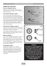
Page 19: ...ator only is lit Phased shutdown In use when the Start stop button is pressed power is switched off to the elements Water will continue to flow for a few seconds flushing out any remaining hot water This makes sure the next immediate user will not receive a slug of hot water if standing under the showerhead when starting the shower Temperature limiter During normal operation if an overheat tempera...

Page 20: ...isit from a qualified engineer to determine the nature of the fault and replace the safety device once the unit has been repaired CLEANING W 007 A WARNING DO NOT use abrasive or aggressive cleaning products when cleaning the shower as they may damage the unit G 004 A Triton Showers recommend that all products are cleaned using warm soapy water Do not use abrasive or aggressive chemical cleaning pr...

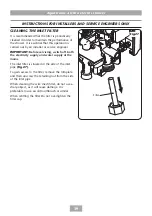
Page 21: ...er or service engineer IMPORTANT Before servicing switch off both the electricity supply and water supply at the mains The inlet filter is situated in the side of the inlet pipe fig To gain access to the filter remove the trimplate and then unscrew the retaining nut from the side of the inlet pipe When cleaning the wire mesh filter do not use a sharp object as it will cause damage It is preferable...

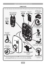
Page 22: ...assembly P12120801 Heater can assembly 9 5kW P12120705 Pressure relief device PRD 82800450 Cover assembly White including Control PCB Start Stop switch LED assemblies S22730600 Cover assembly Chrome including Control PCB Start Stop switch LED assemblies S22730602 Start Stop switch assembly 82301360 LED assembly P12130901 Outlet pipe assembly S12711003 Trimplate white 7053638 Trimplate Grey 7053784...

Page 23: ...rvice Reduce flow rate via temperature control Is water supply mains or tank fed If tank fed replumb to mains water supply or see 4 2 4 If mains fed make sure that the mains stopvalve is fully open and there are no other restrictions in the supply while shower is in use or see 4 2 4 Fit pump to give minimum pressure see rating label Contact Customer Service for advice Readjust flow rate to give re...

Page 24: ...witch Replace solenoid valve Have unit checked Ring Customer Service 4 2 3 4 2 4 4 3 1 4 3 2 4 4 1 5 1 1 6 1 1 6 2 1 6 3 1 6 4 1 7 1 1 7 2 1 7 3 1 required see rating label Reduction in ambient water temperature Electrical malfunction or safety cut out operated Water pressure has dropped below minimum required Blocked showerhead Twisted blocked flexible shower hose Showerhead not removed while com...

Page 25: ...Aquatronic 4 Ultra electric shower 23 ...

Page 26: ...Aquatronic 4 Ultra electric shower 24 ...

Page 27: ...Aquatronic 4 Ultra electric shower 25 ...

Page 28: ...f a complaint occurring the following procedure should be followed 1 Telephone Customer Service on 0844 980 0735 having available the model number and power rating of the product together with the date of purchase 2 Customer Service will be able to confirm whether the fault can be rectified by either the provision of a replacement part or a site visit from a qualified service engineer 3 If a servi...

Reviews: