Whittier Wood 498W Assembly Instructions Manual Download Page 11

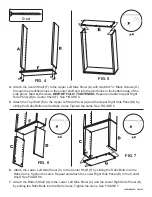
panel lateral. Inicie ambos tornillos 

ANTES DE 

ATORNILLARLOS FIRMEMENTE.

 Repita el 

procedimiento para sujetar el panel lateral superior de-
recho (B) al estante central (F). Vea la FIGURA 4. 

5.

 Sujete el estante superior (E) al panel lateral superior 
izquierdo (A) y al panel lateral superior derecho (B) 
introduciendo los pernos Rafix en las levas Rafix. 
Apriete las levas. Vea la FIGURA 5. 

6.

Sujete el panel lateral inferior izquierdo (C) al estante 
central (F) introduciendo los pernos Rafix en las le-
vas Rafix. Apriete las levas. Repita el procedimiento 
para sujetar el panel lateral inferior derecho (D) al 
estante central. Vea la FIGURA 6. 

7.

 Sujete el estante inferior (G) al panel lateral infer-
ior izquierdo (C) y al panel lateral inferior derecho 
(D) deslizando los pernos Rafix en las levas Rafix. 
Apriete las levas. Vea la FIGURA 7. 

8.

Fije la moldura de corona (I) y la base (J) introdu-
ciendo los pernos Rafix en las levas Rafix. Apriete 
las levas. Vea la FIGURA 8. 

ENCUADRE LA SECCIÓN SUPERIOR: 
9.

Coloque el mueble boca abajo sobre una superficie 
protectora. Mida desde la esquina superior izquierda 
del mueble hasta la esquina derecha del estante 
central 

 y desde la esquina izquierda del es-

tante central hasta la esquina superior derecha del 
mueble 

. Ambas medidas deben ser iguales. 

Si la línea 

 es más larga, golpee suavemente 

la esquina izquierda del estante central hasta que 
las dos medidas sean iguales. Si la línea 

 es 

más larga, golpee suavemente la esquina derecha 
del estante central. Vea la FIGURA 9. 
Fije el panel superior posterior (K) al mueble 
utilizando los orificios pre-taladrados en el panel 
posterior, usando tornillos Philtruss #6 x 5/8" (P). 
El panel debe quedar al ras con el estante superior 
y centrado entre ambos lados. Tenga cuidado de no 
apretar los tornillos excesivamente, porque podría 
dañar la madera.

ENCUADRE LA SECCIÓN INFERIOR: 
10.

Con el mueble boca abajo sobre una superficie 
protectora, mida desde la esquina izquierda del 
estante central hasta la esquina inferior derecha 
del mueble 

 y desde la esquina inferior 

izquierda del mueble hasta la esquina derecha del 
estante central 

. Ambas medidas deben ser 

iguales. Si la línea 

 es más larga, golpee 

suavemente la esquina inferior izquierda del mue-
ble hasta que las medidas sean iguales. Si la línea 

 es más larga, golpee suavemente la esquina 

inferior derecha del mueble. Vea la FIGURA 10

Fije el panel inferior posterior (L) al mueble uti-
lizando los orificios pre-taladrados en el panel 
posterior, usando tornillos Philtruss #6 x 5/8" (P). 
El panel debe quedar al ras con el estante inferior 
y centrado entre ambos lados. Tenga cuidado de no 
apretar los tornillos excesivamente, porque podría 
dañar la madera
Atornille cuatro tornillos Philtruss #6 x 5/8" (P) 
con arandelas de acabado (Q) entre los paneles 
posteriores en el estante central (F). Los tornillos 
deben estar alineados con los tornillos en  los 
paneles posteriores superior e inferior. Vea la 
FIGURA 10. 

INTRODUZCA LAS TACHUELAS 
PROTECTORAS: 
11. 

Golpee suavemente las tachuelas protectoras (R) en 
los paneles laterales inferiores (C y D) cerca de la 
parte posterior. 

Enrosque las tuercas niveladoras 

ajustables (S) en las piezas de plástico (T). Vea la 
FIGURA 11a. Golpee suavemente introduciéndo-
las en los orificios de los paneles laterales. Vea la 
FIGURA 11.

INSTALE LOS ESTANTES AJUSTABLES: 
12.

Coloque el mueble parado derecho. Determine 
dónde desea colocar los estantes ajustables (H). 
Golpee suavemente los soportes para los estantes 
(U) introduciéndolos en los cuatro agujeros, con el 
lado plano hacia abajo, para soportar cada estante. 
Instale los estantes como se ve en la FIGURE 12. 
Puede fijar los estantes introduciendo un tornillo 
rebajado #6 x 1/2" (W) a través del orificio en la 
parte inferior del soporte del estante y atornillándolo 
en el estante ajustable. Vea la FIGURA 12a. 

NIVELE LAS ESTANTERÍAS: 
13.

Haga girar las tuercas niveladoras ajustables hasta 
que el ueble quede nivelado.

FIG. 14 — Stud = Poste

Top shelf = Estante superior

Side panel = Panel lateral

PARA FIJAR EL DISPOSITIVO DE SUJECIÓN:
14.

  Coloque el mueble contra la pared en el lugar 

deseado. Localice el poste en la pared detrás del 
mueble. Sujete el dispositivo de sujeción en forma 
de “L” (X) al poste de la pared con un tornillo de 
cabeza troncocónica #8 x 1¼" (Y) de manera que 
la otra mitad del soporte pueda fijarse al estante 
superior (E) del mueble con un tornillo de cabeza 
troncocónica #8 x 5/8" (Z). Vea la FIGURA 14. Si 
no puede encontrar el poste de la pared, compre 
la sujeción adecuada a su tipo de pared y fije el 
mueble.

498W & 499W  — PAGE 3 SP

Summary of Contents for 498W

Page 1: ...RGLFDOO IRU DQ ORRVH JOXH MRLQWV RU VFUHZV RU DQ RWKHU SUREOHP ZKLFK PD EH DIIHFWLQJ WKH VWDELOLW RI RXU IXUQLWXUH 7LJKWHQ RU UHSDLU DV QHHGHG 6HUYLFH 3ROLF H ZLOO UHSODFH DQ SDUWV ZKLFK DUH GHIHFWLYH PLVVLQJ RU GDPDJHG GXULQJ DVVHPEO 3OHDVH FRQWDFW KLWWLHU RRG 3URGXFWV FXVWRPHU VHUYLFH GHSDUWPHQW GLUHFWO E SKRQH ID PDLO RU HPDLO IRU UHSODFHPHQW SDUWV RXUV 2XU IULHQGO FXVWRPHU VHUYLFH VWDII FDQ EH...

Page 2: ...nsert Qty 2 HARDWARE Q Finish Washer Qty 4 X L Angle Bracket Qty 1 P 6x5 8 Philtruss Screw 498W Qty 30 499W Qty 32 W 6x1 2 Undercut Screw 498W Qty 12 499W Qty 16 Y 8x1 Pan Head Screw Qty 1 Z 8x5 8 Pan Head Screw Qty 1 A Upper Left Side Panel Qty 1 B Upper Right Side Panel Qty 1 C Lower Left Side Panel Qty 1 D Lower Right Side Panel Qty 1 F Center Shelf Qty 1 G Bottom Shelf Qty 1 I Crown Moulding Q...

Page 3: ...shing Hints sheet Note Due to the fact that more than one type of hardwood is used we recommend testing for desired color To test for desired color on a Veneer parts apply stain to unexposed portion of side panels See FIGURE 2 b Alder pieces apply stain to back of base See FIGURE 3 1 Lay out the wood parts in their approximate locations to aid in the identification and assembly FIG 1 498W Wall Uni...

Page 4: ...crew Rafix Bolts N 2 in the Lower Left Side Panel C 2 in the Lower Right Side Panel D 4 in Center Shelf F NOTE These bolts must go in outer holes 2 in the Lower Left Side Panel C 2 in the Lower Right Side Panel D 3 in the Base J 3 in the Crown Moulding I 2 in Upper Left Side Panel A 2 in Upper Right Side Panel B M M M M M M M M M M M M M M M M M M N N N N N N N N N N N N N N N N N N ...

Page 5: ...Top Shelf E to the Upper Left Side Panel A and the Upper Right Side Panel B by sliding the Rafix Bolts into the Rafix Cams Tighten the cams See FIGURE 5 FIG 5 O x4 6 Attach the Lower Left Side Panel C to the Center Shelf F by sliding the Rafix Bolts into the Rafix Cams Tighten the cams Repeat and attach the Lower Right Side Panel D to the Center Shelf See FIGURE 6 FIG 6 7 Attach the Bottom Shelf G...

Page 6: ... bottom left corner of Center Shelf to top right of unit Measurements should be equal If line is longer tap left corner of Center Shelf until measurements are equal If line is longer tap right corner of Center Shelf See FIGURE 9 Fasten the Upper Back Panel K to the unit through the pre drilled holes in the back panel using the 6x5 8 Philtruss Screw P Line up flush to top of Top Shelf and centered ...

Page 7: ... the unit through the pre drilled holes in the back panel using the 6x5 8 Philtruss Screw P Back should line up flush to Bottom Shelf and centered side to side Be careful not to over tighten the screws as you might strip the wood Screw four 6x5 8 Philtruss Screws P with Finish Washers Q between the back panels into the Center Shelf F Screws should line up with screws in the Upper and Lower Back Pa...

Page 8: ...he shelf bracket and screwing it into the adjustable shelf See FIGURE 12a TO LEVEL THE UNIT 13 Rotate adjustable glides until unit stands level x12 498W x16 499W W x12 498W x16 499W U TO ATTACH TIPPING RESTRAINT 14 Position wall unit at desired location Locate stud in wall behind unit Attach L Angle Bracket X to wall stud with 8x1 Pan Head Screw Y so that the other half of bracket may be attached ...

Page 9: ...XJHQH 25 86 6yOR SDUD XVR GRPpVWLFR VH UHFRPLHQGD SDUD XVR FRPHUFLDO HOLFLWDFLRQHV VWH ILQR PXHEOH VHUi XQD EHOOD DGLFLyQ SDUD VX KRJDU 3DUD REWHQHU HO PHMRU UHVXOWDGR FRPLHQFH OH HQGR WDQWR ODV QVWUXFFLRQHV SDUD UPDU FRPR ODV 6XJHUHQFLDV SDUD HO FDEDGR DQWHV GH FRPHQ DU VX SUR HFWR 1R VH VXED QR VH VLHQWH QL VH SDUH VREUH HVWH PXHEOH 1R PXHYD HVWH PXHEOH PLHQWUDV HVWp OOHQR 9DFtHOR DQWHV GH PRYHU...

Page 10: ...s de piezas recibidas coincidan con las indicadas en la lista a continuación 498W y 499W Estanterías Para Libros Modernas Parte Descripción Cantidad 498W 499W A Panel lateral superior izquierdo 1 1 B Panel lateral superior derecho 1 1 C Panel lateral inferior izquierdo 1 1 D Panel lateral inferior derecho 1 1 E Estante superior 1 1 F Estante central 1 1 G Estante inferior 1 1 H Estante ajustable 3...

Page 11: ... golpee suavemente la esquina inferior izquierda del mue ble hasta que las medidas sean iguales Si la línea es más larga golpee suavemente la esquina inferior derecha del mueble Vea la FIGURA 10 Fije el panel inferior posterior L al mueble uti lizando los orificios pre taladrados en el panel posterior usando tornillos Philtruss 6x5 8 P El panel debe quedar al ras con el estante inferior y centrado...

Page 12: ...RXV UHPDUTXH WRXW DXWUH SUREOqPH ULVTXDQW G DIIHFWHU OD VWDELOLWp GX PHXEOH 5HVVHUUH RX UpSDUH DX EHVRLQ 3RXU XVDJH PpQDJHU QRUPDO VHXOHPHQW UHFRPPDQGp SRXU XVDJH FRPPHUFLDO 3ROLWLTXH GH VHUYLFH 1RXV UHPSODFHURQV WRXWHV OHV SLqFHV GpIHFWXHXVHV PDQTXDQWHV RX HQGRP PDJpHV SHQGDQW OH PRQWDJH 9HXLOOH FRQWDFWHU GLUHFWHPHQW OH VHUYLFH FOLHQWqOH GH KLWWLHU RRG 3URGXFWV SDU WpOpSKRQH ID FRXUULHU RX H PDLO...

Page 13: ...eurs types de bois dur sont utilisés nous recommandons de procéder à des tests pour obtenir la couleur désirée Pour tester la couleur désirée sur a Des pièces en placage appliquez la teinture sur une portion non visible des panneaux latéraux Voir la FIGURE 2 b Des pièces en aulne appliquez la teinture sur l arrière de la base Voir la FIGURE 3 INSTRUCTIONS DE MONTAGE OUTILS NÉCESSAIRES Tournevis cr...

Page 14: ...ype de mur et assujettissez le meuble 4 Fixez l étagère centrale F au panneau latéral supérieur gauche A au moyen de deux vis noires no 8x15 8 po O que vous introduisez dans les trous préforés ménagés dans l étagère centrale puis dans les trous de guidage ménagés dans le bord inférieur du panneau latéral Introduisez les deux vis AVANT DE LES SERRER COMPLÈTEMENT Répétez la procédure pour monter le ...

Reviews: