background image

15 


plate and over the threads of the M10 bolts 
between the bracket and the Blade 
backplate. 

8.3.3


Repeat for the other end of the Blade if 
necessary. 

8.3.4


Set the Blade to the required height below 
the railhead using a suitable gauge / 
measuring device minimum distance is 
18mm. The precise dimension is subject to 
rail profile and anticipated wheel wear, 
which must be carefully considered. If 
required a suitable gauge is available from 
Whitmore Rail (Part No. or LCS104-06), 
showing setting with QHi/Whitmore Rail 
gauge). 
 

8.3.5


Repeat from 8.3.1 for the remaining blades. 

8.4


Application Variation for Other Rail Types 

8.4.1


The fitting process is the same for the Bull 
Head and UIC60 style Blades; only the Blade 
bracket is different. 


8.5


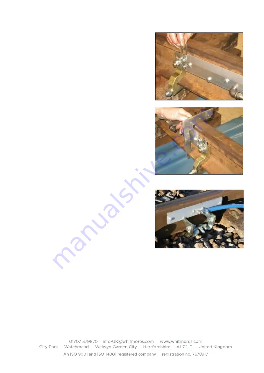
Installing EasiBlades (single central rail clamp) 

8.5.1


EasiBlades are supplied as complete single 
units. From the 4’ / Gage and midway 
between Sleepers / Ties slide the base (W 
bracket) over the rail foot as shown. Locate 
the hook bolt around the opposite side of the 
foot and tighten the single Nyloc nut. Fully 
bed the base onto the rail using a hammer on 
the vertical faces of the ‘W’ bracket.  
Retighten the Nyloc nut. 

8.5.2


The blades are provided in left and right hand forms; the difference being the direction the 
hose tail points, the correct layout is shown in the adjacent picture, outer pairs with hose 
tails pointing towards each other. 

8.5.3


Tilt the blade up so that the blade tip is towards the rail head and as high as possible, 
lightly tighten the two pivot bolts. 

Summary of Contents for LUBRICURVE 50

Page 1: ...LUBRICURVE 50 Installation Maintenance Manual TRACK MOUNTED MECHANICAL RAIL AND WHEEL FLANGE LUBRICATOR SYSTEM Model Variants 2 Blade Systems 4 Blade Systems EasiBlades Standard Blades ...

Page 2: ... Clamp 14 8 3 Installing the Blades 14 8 4 Application Variation for Other Rail Types 15 8 5 Installing EasiBlades single central rail clamp 15 8 6 Installing Check Rail Blades 16 9 Final Setting 18 9 1 Fitting the Delivery Hoses 18 9 2 Fill the Hoses and Blades 18 9 3 Fit the Pump Guard 18 10 Routine Maintenance 19 Prior to any maintenance it is necessary to have the following data 19 10 1 Measur...

Page 3: ...ottom rails and 95lb bull head rail applications Only lubricator grease approved for use by Whitmore Rail can be used in the LubriCurve system Use of other greases will invalidate warranty 2 Product Transport Storage Goods are packed and delivered to requested address in a form that is suitable for the product given good practice in the off loading by the receiving company LubriCurve 50 systems ar...

Page 4: ...se The feed hose transfers the grease from the reservoir to the pump inlet pipework Blade Grease Dispensing Unit There are generally two or four Blades used with each lubricator each consisting of three rectangular plates back plate middle plate and grooved front plate Each Blade is fitted to the rail using two rail clamps which are secured to the rail by a hook bolt nut and washer per clamp The B...

Page 5: ...2 5mm Allen key that is adjusted from the top of each pump body to adjust the height of the plunger A pressure pad operates on the side of the adjuster screw The higher the plunger in relation to the top of the rail the greater the grease output Plunger Return Spring There is one plunger return spring in each pump body The springs return the plungers to its static position after the plunger has be...

Page 6: ...t secure the pump and the Blades The equipment needed for this work is o A shovel or ballast fork whichever one is the most suitable o All relevant P P E needed to carry out the works safely The lubrication systems outlined are heavy and care should be taken in general safe mechanical handling of the units to the install site Two people should handle pump storage boxes typically 28kg and reservoir...

Page 7: ...and that they are fully tightened Ensure that each pump body has one grease outlet pipe attached Ensure that the plunger is able to be depressed manually and returns freely Blade Ensure that it is not bent or damaged and all ports are free from blockages Ensure that all bolts are present and are fitted securely Ensure that the hose inlet tails which the delivery hoses attach to are in place and ar...

Page 8: ... following images one pair of blades to the right of the pump reservoir and on the same rail and the second pair of blades on the far rail and to the left of the pump reservoir Each pair of blades has a T piece midway between the blades and the hose from the T s vertical leg routes to each of the pump bodies The hose between each blade and the T must be of identical length Plunger heights are gene...

Page 9: ...ead rail 7 3 1 Rail clamps are of a different form for the Bull Head Rail The clamps consist of two sections that fit around the rail flange 7 3 2 The main part of the clamp hole and machined slot is fitted on the field outside side of the rail Locate the 70mm 3 long special hex bolts through the upper holes of the clamp with the hexagon head located in the clamp slot before fitting to rail 7 3 3 ...

Page 10: ...p bracket fit the pump unit onto the clamp studs Place M16 packing washers over the Rail Clamp stud and behind the pump bracket such that the pump bracket is not strained on tightening of the fixings and that the pump body is touching the railhead 7 4 6 Push the pump unit down as low as possible fit one M16 flat washer and full nut to each stud and tighten 7 4 7 Ensure the plunger and adjusting sc...

Page 11: ...Remove the filler dust cap and store safely Attach a suitable drum pump to the 3 4 snaplock filling point and secure locking arms in the clamp position Operate the hand pump measuring piston depth periodically to a reading of 80mm from reservoir front plate to rear most surface of piston Do not overfill the reservoir Flat Back Plate older reservoirs Top Hat Back Plate newer reservoirs Full 80mm Fu...

Page 12: ...to lean the plungers towards the railhead then secure the two M8 fixings on each pump body 7 7 5 Using a suitable gauge measurement device and 2 5mm Allen key raise the plungers to their initial setting height of 0 5mm above the top of the rail Note Subsequent adjustment is usually necessary to the adjust grease output to suit local traffic wheel pattern The typical range will be between 0 and 1mm...

Page 13: ...eral oil grease contamination removed and Loctite 222 Whitmore Rail Part No LCS200 69 applied to the thread prior to re fitting New adjusting screws can be obtained see parts list LCS200 22 A plunger setting gauge is available from Whitmore Rail should that be preferred Part No LCS104 06 7 8 Test the Pumping System 7 8 1 Using the wood shaft of a suitable hammer or other suitable tool depress one ...

Page 14: ...n for Bull Head Blade Rail Clamp 8 2 1 Blade Rail clamps are different for the Bull Head Rail Clamps consist of two sections to fit around the rail flange 8 2 2 Locate the 50mm 2 long special hex bolts through the upper holes of the clamp with the hexagon head located in the clamp slot The clamp is fitted on the 4 side of the rail with the thread stud at the top and facing away from the rail 8 2 3...

Page 15: ...ame for the Bull Head and UIC60 style Blades only the Blade bracket is different 8 5 Installing EasiBlades single central rail clamp 8 5 1 EasiBlades are supplied as complete single units From the 4 Gage and midway between Sleepers Ties slide the base W bracket over the rail foot as shown Locate the hook bolt around the opposite side of the foot and tighten the single Nyloc nut Fully bed the base ...

Page 16: ...over the vertical face of the rail clamp If there is any clearance before tightening then insert suitable M16 washers between the two items to reduce clearance 8 5 7 Repeat process for each EasiBlade 8 6 Installing Check Rail Blades The procedure is similar to a standard Blade installation on the high rail Confirm that the check rail blades are fitted only to the check rail Note Rails can take sev...

Page 17: ... insufficient clearance between the foot of the running rail and foot of the check rail then a rail clamp is fitted to each rail and long stud in between passing under the two rails The check blade must be located at the check block to avoid over stressing the between the rail fastener 8 6 3 Locate the Check Rail assembly on the two rail clamp studs and tighten the two M16 fasteners securely 8 6 4...

Page 18: ... minimum 1mm clearance with pump body 9 2 2 Repeat for the other Blade Alternative The operation can be made more efficient by using the Blade priming kit available from Whitmore Europe Part No LCS102 08 Prior to filling the delivery hose to the pump body outlet Insert the filler connector into the free end of the delivery hose and clamp with the provided hose clip Connect the reservoir hand pump ...

Page 19: ...e reservoir is at 10 1 3 When the ruler stops at the rear most face of the piston check exactly the measurement in millimetres against the face of the rear cover at the centre hole 10 1 4 Record this measurement and compare it to the data that you have brought to site Important Note Do not overfill the reservoir Flat Back Plate older reservoirs Top Hat Back Plate newer reservoirs Full 80mm Full 80...

Page 20: ...al measurements of the plunger heights There are two measurements to be recorded one for the running on and one for the running off The running on and running off are identified by the direction of traffic the running on being the first plunger that the train wheels will strike and the running off being the second plunger that the train wheels will strike The height to be measured is the distance ...

Page 21: ...xceed the permissible plunger travel Record the results If the attempt to clear the airlock was not satisfactory check that there is a grease flow from the reservoir Repeat the sequence for the remaining plunger Air locks that are present once servicing is done at the lubricator will give you certain information into why the lubricator has not had a sufficient grease output If the lubricator has n...

Page 22: ...g valve is clean place the filling pump nozzle over the non return filling valve on the reservoir and pump the handle 10 9 2 Do not fill the reservoir to more than 80mm 10 9 3 Record the final reservoir measurements 10 10Periodic Replacement of Components 10 10 1 It is recommended that various system items are replaced periodically exchange will be dependent on traffic frequency and should be moni...

Page 23: ...ervoir empty and the spider still in place and locked the rear reservoir securing bolts can be removed Slowly unwind the spider locking handle from against the back plate until all spring pressure is removed DO NOT ATTEMPT THIS PROCESS WITH GREASE IN THE RESERVOIR It is recommended that operatives stand to the side of the reservoir during the dismantling process Exchange Frequency Pump Springs 2 y...

Page 24: ... 7 GDU s 5 Grease Flow Test PASS FAIL PASS FAIL 8 2 If yes number of sleepers YES NO YES NO 7 3 Removed cleaned plates 8 1 Over rail head YES NO YES NO PASS FAIL YES NO YES NO Continuous grease flow 8 Grease distribution through curve 6 4 Replaced pump body YES NO 2 2 Plunger Running off 2 3 Hoses 7 GDU 7 1 Visual check PASS FAIL 7 2 Pumped through GDUs 7 4 Fitted new plates YES NO YES NO PASS FAI...

Page 25: ...llen Key Ratchet Handle 1 2 Drive Combination Spanner 24mm Combination Spanner 20mm Combination Spanner 19mm Combination Spanner 17mm Combination Spanner 13mm Combination Spanner 15 16 Socket 7mm 3 8 drive Socket 13mm 1 2 drive Socket 17mm 1 2 drive Socket 19mm 1 2 drive Socket 24mm 1 2 drive Socket Long Reach 24mm 1 2 drive Ball Pein 1lb Hammer Junior Hacksaw and Blades Screwdriver 6 x 1 4 flat b...

Page 26: ...26 13Exploded Views of System Elements ...

Page 27: ...27 ...

Page 28: ...28 ...

Page 29: ...29 ...

Page 30: ...30 ...

Page 31: ...31 ...

Page 32: ...32 ...

Page 33: ...33 ...

Page 34: ...34 ...

Page 35: ...35 ...

Page 36: ...36 ...

Page 37: ...37 ...

Page 38: ...38 ...

Reviews: