background image

WHITEHALL MANUFACTURING

 • P.O. BOX 3527 • City of Industry, CA 91744-0527 U.S.A

Phone (800) 782-7706 • (626) 968-6681 • Fax (626) 855-4862 • Web: www.whitehallmfg.com

8

Instructions for Operation and Care of Best-Care WH3740

Assemble waste piping using teflon tape on all threaded 

5

connections and make up waste connections to 1-1/2" P-trap.

WASTE ASSEMBLY

HINT: Teflon tape is recommended on all threaded waste and 
supply connections.

3

1
2

"

REF.

4

5
8

" REF.

4

5
8

" REF.

Rubber Gasket

Overflow Adapter

Red Flat Fiber Gasket

1-1/2" - 16 UNI Rough Chrome Brass Nut

1-1/4" - 27 UNI Close Ell w/ 3/8" NPTI Clean-Out

Plug

Waste Outlet Connection

Strainer Flange

11

10

9

8

7

6

5

Strainer w/ 1-1/2" - 16 UNE Threads

4

3/8" O.D. x 3/8" NPT Female Connection

2

Overflow Insert

1

1

2

4

5

6

3/8" O.D. x 3/8" NPT Male Connection

7

5

8

9

10

11

3

3/8" O.D. Overflow Tube

3

NOTE: Waste assembly may require field cutting and fitting by the 
installer.

Install strainer to basin using plumbers putty 

4

on underside of grid strainer flange. Insert the 
Overflow Insert through the Overflow Hole and 
tighten to 3/8” O.D. Elbow Adapter. From 
beneath basin, assemble rubber gaskets, 
overflow adapter, fiber gasket and jam nut as 
shown to strainer and tighten securely. Add 
close elbow to strainer assembly as indicated.

Summary of Contents for WH3374

Page 1: ...Ligature Resistant Stainless Steel Basin Powder Coated White ADA Compliant 6900 198 001 April 2019 Model WH3740 INSTALLATION OPERATIONS AND MAINTENANCE MANUAL WH3740 WH3374 ...

Page 2: ...owner or maintenance personnel upon completion of installation Teflon tape is recommended on all threaded waste and supply connections to reduce the possibility of leaks ANSI UFAS or ADA compliance is subject to the interpretation and requirements of the local code authority and is the responsibility of the installer for verification Provide 110 120VAC 60Hz 3A MAX electrical receptacle for factory...

Page 3: ...air Parts 19 21 Warranty Information 22 PAGE Required Items for Installation Not Supplied Carpenters Level 1 2 NPS Flexible Supply Hose For Dual Temperature with Tempering Valves Only Chalk Line Hammer 1 2 NPS Outlet Angle Stops 5 8 Hex Wrench 1 8 Allen Wrench for Temperature Adjustment 1 8 Slotted Tip Screwdriver For Metering Adjustment Fixture Wall Anchors and Anchoring Hardware and Appropriate ...

Page 4: ... 626 968 6681 Fax 626 855 4862 Web www whitehallmfg com 2 ADA Adult ADA ages 6 thru 12 ACCESSIBILITY OVERVIEW Instructions for Operation and Care of Best Care WH3740 OBC 211 2 211 2 27 Min 4 31 Rim Max 253 8 85 8 27 Min 4 34 Rim Max 115 8 253 8 OBC PROFILE 211 2 29 Min 4 33 Rim Max 105 8 253 8 ...

Page 5: ... P O BOX 3527 City of Industry CA 91744 0527 U S A Phone 800 782 7706 626 968 6681 Fax 626 855 4862 Web www whitehallmfg com 3 DIMENSIONAL DATA 19 3 253 8 163 8 4 211 2 Instructions for Operation and Care of Best Care WH3740 ...

Page 6: ...g Holes for Ø1 1 2 Tube Lavy Waste Outlet For Compression Joint 1 2 NPS Hot Cold Angle Stops By Others A B C D E 120VAC 60Hz 3A Max GFCI Protected Electrical Receptacle F 23 8 81 2 Typ A B 3 Ø1 4 Mounting Holes G 2 Ø9 32 Mounting Holes for Valve Mounting Bracket D C 2 4 41 2 E 71 8 41 2 F 6 Typ 351 2 2 Ø9 32 x 3 4 Long Mounting Slots for 1 4 Wall Anchors 3 8 Wall Anchors with min Pull Out Force of...

Page 7: ... 4 Wide Mounting S Clip w Fixture Support Mounting 4 Ø9 16 Mounting Holes for Ø1 1 2 Tube Lavy Waste Outlet For Compression Joint 1 2 NPS Hot Cold Angle Stops By Others A B C D E 120VAC 60Hz 3A Max GFCI Protected Electrical Receptacle F 3 Ø1 4 Mounting Holes G 2 Ø9 32 Mounting Holes for Valve Mounting Bracket 2 Ø9 32 x 3 4 Long Mounting Slots for 1 4 Wall Anchors 3 8 Wall Anchors with min Pull Out...

Page 8: ...unting S Clip w Fixture Support Mounting 4 Ø9 16 Mounting Holes for Ø1 1 2 Tube Lavy Waste Outlet For Compression Joint 1 2 NPS Hot Cold Angle Stops By Others A B C D E 120VAC 60Hz 3A Max GFCI Protected Electrical Receptacle F 3 Ø1 4 Mounting Holes G 2 Ø9 32 Mounting Holes for Valve Mounting Bracket 2 Ø9 32 x 3 4 Long Mounting Slots for 1 4 Wall Anchors 3 8 Wall Anchors with min Pull Out Force of ...

Page 9: ... 1000 lbs per anchor is required Once the valve mounting bracket is anchored to the 2wall mount the valve assembly to the valve mounting bracket using mounting hardware provided by the installer Before anchoring basin to the wall remove waste 3assembly After the waste assembly has been removed install mounting hardware to fixture Center and butt the basin to the finished wall Slide down the basin ...

Page 10: ...me Brass Nut 1 1 4 27 UNI Close Ell w 3 8 NPTI Clean Out Plug Waste Outlet Connection Strainer Flange 11 10 9 8 7 6 5 Strainer w 1 1 2 16 UNE Threads 4 3 8 O D x 3 8 NPT Female Connection 2 Overflow Insert 1 1 2 4 5 6 3 8 O D x 3 8 NPT Male Connection 7 5 8 9 10 11 3 3 8 O D Overflow Tube 3 NOTE Waste assembly may require field cutting and fitting by the installer Install strainer to basin using p...

Page 11: ...valve to spout s using 1 4 OD tubing and adapter NOTE Installation should be in accordance with accepted plumbing practices Angle stops are recommended and is the responsibility of the installer MXTP VALVE ONLY 5 Turn on fixture and allow water to flow for 2 minutes Measure water temperature at outlet If water is not at desired temperature adjust as necessary 1 Locate suitable place for mounting t...

Page 12: ...sing a 3 8 wrench to retain 10 32 hex nuts 2 to free valve assembly with valve bracket 3 Once screws nuts and washers 4 have been removed place in a safe place for reassembly 3 With valve assembly free from wall bracket 5 remove 10 32 phillips screw s 6 from the back of the valve bracket 3 to allow valves 7 to be free 5 Reassemble in reverse order 7 Air within the valve assembly or the structure s...

Page 13: ...n Ferrule Nut Leave a minimum 1 4 of polyethylene tubing protruding through the Ferrule Nut This is necessary to ensure proper tubing connection Ferrule Nut Timing Screw To adjust timing turn timing screw Turn timing screw clockwise to increase timing Do not over tighten ferrule nuts 1 8 O D AIR TUBE 1 4 O D WATER TUBE Instructions for Operation and Care of Best Care WH3740 ...

Page 14: ...sensor and make short circuit on red wires See DETAIL A 2 Connect power supply to sensor Red light should be flashing 3 Move hand in front of sensor to distance of 2 to 4 within 5 seconds and wait until red light flashes quickly 4 Move hand to desired sensing distance See DETAIL B DETAIL A DETAIL B DETAIL C Transformer must be plugged into a GFI protected circuit Fixture must be earth grounded per...

Page 15: ...6 968 6681 Fax 626 855 4862 Web www whitehallmfg com 13 Instructions for Operation and Care of Best Care WH3740 ACCESS PANEL INSTALLATION Install P Trap cover using 10 32 x 1 2 center reject hex head screws provided Secure bottom of P Trap cover to wall with anchoring hardware provided by others ...

Page 16: ...ervomotor seat is damage Replace servomotor seat Servomotor plate or diaphragm is obstructed Servomotor timer assembly is damaged Replace servomotor timer assembly Probable Cause Solution Valve riser tubing is crimped Straighten valve riser tubing Debris or scale in checkstop strainer Remove checkstop strainer and clean Blockage in valve flow control Remove blockage Low water pressure at supplies ...

Page 17: ...ecommended Apply the stainless steel cleaner polish to the synthetic abrasive pad and CAREFULLY rub out spot with cleaner polish Be sure to rub in the direction of the grain Do not allow steel wool to come in contact with stainless steel Steel particles can embed into the stainless steel surface and create rust To remove rust stains Wipe surfaces with CRES available from Acorn or equivalent cleane...

Page 18: ...ill go out now you are in the 1 sec timing mode and each time the button is pushed the LED will flash adding 1 sec to the total timing cycle To move on to the 5 sec timing mode pause and wait for the LED to flash 2 times now you are in the 5 sec timing mode Each time the button is pushed the LED will flash adding 5 sec to the total timing cycle To move on to the 20 sec timing mode pause and wait f...

Page 19: ... equals 20 sec added to the total timing cycle Ÿ LED flashes then stays on Ÿ While the LED is steady on push button Ÿ LED turns off Ÿ Reconnect power Ÿ You are in the 1 sec timing mode immediately push the button 1 push equals 1 sec added to the total timing cycle Ÿ You are in the 5 sec timing mode immediately push the button 1 push equals 5 sec added to the total timing cycle Ÿ Pause and wait for...

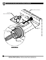
Page 20: ...y of Industry CA 91744 0527 U S A Phone 800 782 7706 626 968 6681 Fax 626 855 4862 Web www whitehallmfg com 18 Piezo Pushbutton Programing Indicator LED Light LIGHT DETAIL Red Power Cable Lavy Shown for reference 3774 PPZ Shown For Reference Transparent Epoxy Filling Black Red Black Solenoid Cable ...

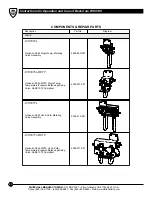
Page 21: ... 199 4953 001 000 1 1 2 OD Tubular P Trap P Trap Cover 6207 331 199 Ligature Resistant Elbow Strainer 4926 080 001 COMPONENTS REPAIR PARTS Description Part No Diagram ENCLOSURES 10 32 UNF x 1 2 S S Phil Truss HD Screw 0116 010 000 0112 002 000 COMBINED WASTE ASSEMBLY 4970 180 001 1 1 4 OD Waste Bend Connection ELECTRONIC HARDWARE 9 VDC Battery Pak Assy 6 AA Batteries Not Included Battery Pak Mount...

Page 22: ...PAIR PARTS Description Part No VALVE Diagram 2590 900 001 Optional 03 M Single Temp Metering Valve Assembly Optional 03 M MXTP Single Temp Temperature Pressure Balancing Mixing Valve ASSE 1070 Compliant 2590 901 001 Optional 04 M MXTP Hot Cold Temperature Pressure Balancing Mixing Valve ASSE 1070 Compliant 2590 911 001 Optional 04 M Hot Cold Metering Valve Assembly 2590 910 001 WH3376L WH3376L MXT...

Page 23: ...Metering Valve Assembly Single Temperature Optional Electronic Metering Valve Assembly Single Temp Temperature Pressure Balancing Mixing Valve ASSE 1070 Compliant 2590 906 001 Optional Electronic Metering Valve Assembly Hot and Cold Temperature Pressure Balancing Mixing Valve ASSE 1070 Compliant 2590 916 001 Optional Electronic Metering Valve Assembly Hot and Cold 2590 915 001 WH3377L PPZ WH3375L ...

Page 24: ...e instructions are issued with each fixture and disregard or non compliance with these instructions will constitute an abnormal use condition and void the warranty If you have any questions or require technical assistance please call 800 743 8219 Go to to fill out eWarranty Registration keyword search WARRANTY www whitehallmfg com Whitehall Manufacturing Company warrants that its products are free...

Reviews: