4
Installation Configuration Options
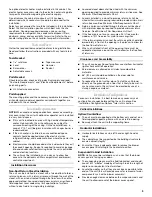
NOTE: Typical installations with optional WMAH modular
evaporator coil are shown.
Applications—Upflow/Counterflow
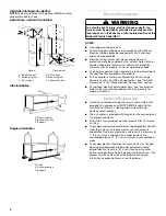
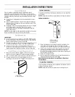
Attic Installation
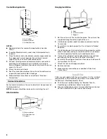
Hanging Installation
Electrical Requirements
NOTES:
■
Use copper conductors only.
■
All field wiring must be done in accordance with National
Electrical Code, applicable requirements of UL and local
codes where applicable.
■
Electrical wiring, disconnect means and overcurrent
protection are to be supplied by the installer. Refer to the air
handler rating plate for maximum overcurrent protection,
minimum circuit ampacity, as well as operating voltage.
■
The power supply must be sized and protected according to
the specifications supplied on the product.
■
This air handler is factory-configured for 240-volt, single
phase, 60 cycles. For 208-volt applications, see “208-Volt
Conversion” in the “Make Electrical Connections” section.
■
For optional electric heater applications, see “Accessories.”
Refer to the instructions provided with the accessory for
proper installation.
Ductwork Requirements
■
Install the conditioned air plenum, ducts and air filters (not
provided) in accordance with NFPA 90B Standard for the
Installation of Warm Air Heating and Air-Conditioning
Systems (latest edition).
■
The air handler is provided with flanges for the connection of
the plenum and ducts.
■
All air filters (not provided) must be listed as Class 2 furnace
air filters.
■
The supply and return ductwork must be adequately sized to
meet the system’s air requirements and static pressure
capabilities. Ductwork should be insulated with a minimum of
1" (2.5 cm) thick insulation with a vapor barrier in the
conditioned areas or 2" (5.1 cm) minimum in unconditioned
areas.
■
The supply plenum should be the same size as the flanged
opening provided around the blower outlet and should
extend ideally at least 36" (91.4 cm) from the air handler
before turning or branching off plenum into the duct runs. The
plenum forms an extension of the blower housing and
minimizes air expansion losses from the blower.
Upflow
A. Blower cabinet
B. Airflow direction
C. Coil cabinet
Counterflow
A. Coil cabinet
B. Blower cabinet
C. Airflow direction
A. Blower cabinet
B. Airflow direction
C. Support
A. Rods
B. Airflow direction
C. Support
A
B
C
A
B
C
A
B
C
A
B
C
A
Goodman 31
WARNING
To avoid the risk of injury, electrical shock or death, the
furnace must be electrically grounded in accordance with
local codes or, in their absence, with the latest edition of the
National Electric Code (NEC).


