13
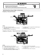
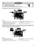
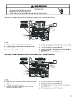
Heat Pump—2-Stage Emergency Heat and 2-Stage Auxiliary Heat—2 Outdoor Thermostats
NOTES:
■
No auxiliary heat in heat pump mode until outdoor thermostat
closes.
1. Y enables high speed fan cooling.
2. E enables low speed fan heating. W2 with OT1 closed
enables low speed fan heating. W2 with OT2 closed enables
high speed fan heating.
3. OT1 PJ4 must be cut for this configuration.
4. OT2 PJ2 must be cut for this configuration.
5. Cut HUM PJ6 jumper if using humidistat. Humidistat opens
on humidity rise.
6. DIP Switch 4 must be in the “ON” position.
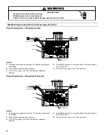
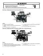
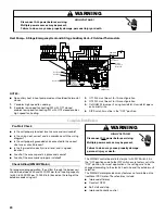
Heat Pump—2-Stage Emergency Heat and 1-Stage Auxiliary Heat—1 Outdoor Thermostat
NOTES:
■
No auxiliary heat in heat pump mode until outdoor thermostat
closes.
1. Y enables high speed fan cooling.
2. E enables low speed fan heating. W2 with OT2 closed
enables high speed fan heating.
3. OT1 PJ4 must be cut for this configuration.
4. OT2 PJ2 must be cut for this configuration.
5. Cut HUM PJ6 jumper if using humidistat. Humidistat opens
on humidity rise.
6. DIP Switch 4 must be in the “ON” position.
Goodman 6 Long
HIGH VOLTAGE!
WARNING
Disconnect ALL power before servicing.
Multiple power sources may be present.
Failure to do so may cause property damage, personal injury or death.
Please refer
to manual
for proper
DIP switch (CFM)
configuration.
If Needed
2
nd
Stage Heater
Humidistat
(Optional)
Room Thermostat
1
st
Stage Heater
See Note 5
Remove
Production
Wire Y1-O
See Note 5
See Note 4
Heat Pump
See Note 3
OT2
W1
OT1
O
W/W2
OTC
R
OT1
OT2
W2
W1
YCON
O
W2
OUTDOOR
O
R
YCON
O
W2
O
G
Y1
R
C
W2
24 VAC
C
R
Y1
G
If Needed
2
nd
Stage Heater
Humidistat
(Optional)
Room Thermostat
1
st
Stage Heater
See Note 5
Remove
Production
Wire Y1-O
See Note 5
See Note 4
Heat Pump
Outdoor Thermostat
Please refer
to manual
for proper
DIP switch (CFM)
configuration.
See Note 3


