


20
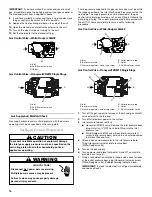
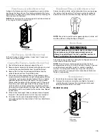
3. Remove the burners.
4. Use a bottle brush to clean burner insert and inside of the
burners.
5. Replace burners and manifold, inspect the burner assembly
for proper seating of burners in retention slots.
6. Reconnect electrical power and gas supply.
For further information on the yearly inspection, consult the User
Manual. It is recommended that a qualified servicer inspect and
service the unit at least once each year.
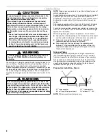
Turn the unit on at the thermostat. Wait a few minutes, since any
dislodged dust will alter the normal flame appearance. Flames
should be predominantly blue and directed into the tubes. They
should not be yellow. They should extend directly outward from
the burner ports without curling downward, floating or lifting off
the ports.
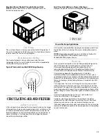
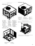
ACCESSORIES AND FUNCTIONAL PARTS
Sheet Metal Accessories
Additional accessories can be purchased to fit specific
application needs. Parts and instructions are available from your
distributor.
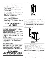
Functional Parts
General Information
■
Refer to the description in Functional Parts List when
ordering any of the listed functional parts. Be sure to provide
the unit model and serial numbers with the order.
■
Although only functional parts are shown, all sheet metal
parts, doors, etc., may be ordered by description.
■
Parts are available from your distributor.
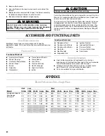
APPENDIX
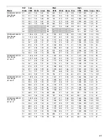
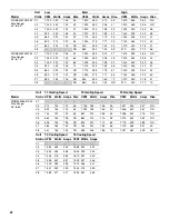
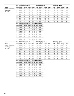
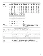
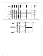
Blower Performance Data—Single Phase
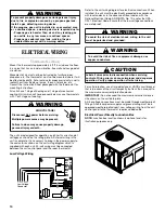
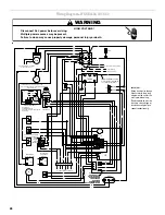
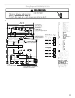
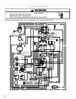
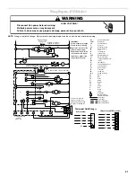
Label all wires prior to disconnection when servicing
controls. Wiring errors can cause improper and dangerous
operation. Verify proper operation after servicing.
WARNING
Always verify proper operation after servicing.
CAUTION
Functional Parts List
■
Auxiliary Limit Switch
■
Blower Housing
■
Circulator Blower Motor
■
Blower Wheel
■
Burner
■
Capacitor
■
Compressor
■
Flame Roll-out Switch
■
Flame Sensor
■
Gas Orifice
■
Gas Control Valve
■
Heat Exchanger
■
High Limit Switch
■
Igniter
Functional Parts List
■
Condenser Coil
■
Condenser Fan Blade
■
Condenser Fan Motor
■
Contactor
■
Gas Manifold
■
Evaporator Coil
■
Ignition Control
■
Induced Draft Blower
■
Pressure Switch
■
Pressure Switch Hose
■
Transformer
Unit
Low
Med
High
Model
Static
CFM
Watts
Amps Rise
CFM
Watts
Amps Rise
CFM
Watts
Amps Rise
WGGE4324A045M
Rise Range:
30º to 60º
0.1
600
150
0.67
57
850
230
1.02
40
1,190
380
1.67
NR
0.2
570
140
0.65
60
830
220
1.00
41
1,140
360
1.62
NR
0.3
510
130
0.63
NR
765
215
0.97
45
1,080
350
1.58
32
0.4
450
125
0.61
NR
715
210
0.94
48
1,025
340
1.54
33
0.5
380
120
0.58
NR
660
205
0.90
52
975
330
1.38
35
0.6
---
---
---
NR
610
195
0.88
56
920
310
1.37
37
0.7
---
---
---
NR
---
---
---
NR
830
300
1.35
41
0.8
---
---
---
NR
---
---
---
NR
730
290
1.32
47


