11
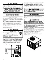
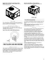
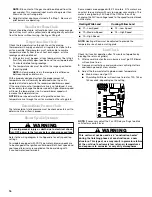
Electrical Power Routed Through Bottom of Unit
NOTE: Junction box location shown is optional and is for
illustration purposes only.
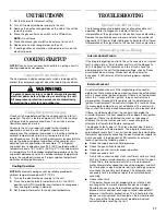
Unit Voltage
The unit transformer is factory-connected for 230V operation. If
the unit is to operate on 208V, reconnect the transformer primary
lead as shown on the unit wiring diagram.
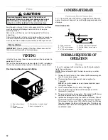
Heat Anticipator Setting
The heat anticipator is to be set by measuring the load
(amperage) at the R circuit. Follow the instructions provided by
the thermostat for more details.
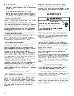
Typical Thermostat and Unit 24V Wiring Hookup
CIRCULATING AIR AND FILTERS
Airflow Conversion
Units can easily be converted from horizontal to down-discharge
airflow delivery. In down-discharge or high-static installations, the
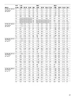
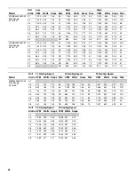
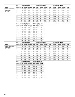
installer should measure the total external static and review the
blower performance charts before performing the installation. In
some installations, it will be necessary to change the blower
speed to provide proper airflow.
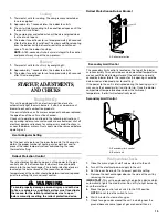
Duct Cover Installations—Down-Discharge
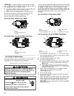
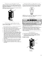
Remove the panels for down-discharge duct applications
Down-Discharge Applications
Cut insulation around bottom openings and remove panels from
the bottom of the unit, saving the screws holding the panels in
place.
NOTE: Single-phase models require installation of horizontal
duct kit #20464501PDGK (medium chassis) and
#20464502PDGK (large chassis).
Ductwork
Duct systems and register sizes must be properly designed for
the C.F.M. and external static pressure rating of the unit.
Ductwork should be designed in accordance with the
recommended methods of Air Conditioning Contractors of
America Manual D (Residential) or Manual Q (Commercial).
All ductwork exposed to the outdoors must include a
weatherproof barrier and adequate insulation. A duct system
should be installed in accordance with Standards of the National
Board of Fire Underwriters for the Installation of Air Conditioning,
Warm Air Heating and Ventilating Systems. Pamphlets No. 90A
and 90B.
The supply duct from the unit through a wall may be installed
without clearance. However, minimum unit clearances must be
maintained. The supply duct should be provided with an access
panel large enough to inspect the air chamber downstream of the
heat exchanger. A cover should be tightly attached to prevent air
leaks.
For duct flange dimensions on the unit, refer to the Unit
Dimension illustration in the Appendix.
For down-discharge applications, the ductwork should be
attached to the roof curb prior to installing the unit. Ductwork
dimensions are shown in the roof curb installation manual.
If desired, supply and return duct connections to the unit may be
made with flexible connections to reduce possible unit operating
sound transmission.
G
Y
W
R
R
W
Y
G
From
Unit
A. Supply air panel
B. Return air panel
A B


