background image

3

INSTALLATION REQUIREMENTS

Tools and Parts

Gather the required tools and parts before starting installation. 
Read and follow the instructions provided with any tools listed 
here.

Tools needed

Through-the-Wall Installation

In addition to the tools listed above, the following tools are 
needed for through-the-wall installation.

Parts supplied

Check that all parts are included in parts package.

Air conditioner installation

SMART-MOUNT

®

 tray assembly installation

Location Requirements

IMPORTANT: Observe all governing codes and ordinances.

Check the location where the air conditioner will be installed. 
Make sure you have everything necessary for correct installation.

The location should provide:

Grounded electrical outlet within 4 ft (122 cm) of where the 
power cord exits the air conditioner. 

NOTE: Do not use an extension cord.

Free movement of air in room to be cooled.

A large enough opening for the air conditioner. Installation 
parts are supplied for double-hung windows.

Adequate wall support for weight of air conditioner. Air 
conditioner weighs 80 lbs (36.3 kg) to 125 lbs (56.7 kg).

NOTE: Cabinet louvers must not be obstructed. Air must be able 
to pass freely through the cabinet louvers. 

Flat-blade and Phillips 
screwdrivers

¹⁄₄

" nut driver

⁷⁄₁₆

" wrench

Scissors

Pencil

Tape measure

Level

Drill 

³⁄₃₂

" or smaller drill bit

Saw

Wood preservative

Caulk

1" (2.5 cm) or thicker 
lumber

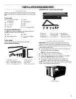
A. Window-lock bracket 
B. #8 x 

³⁄₈

" pan-head screws (6)

C. #8 x 

³⁄₄

" round-head screws (3) 

D. #10 x 

³⁄₈

" pan-head screws (3)

E. Side curtains (2)
F. Top channel

G. Foam seal
H. Side curtain frames (2)

F

A

B

C

D

E

G

H

A. Tray back 
B. Tray center

C. Tray sides (2)
D. Support legs (2)

E. #8 - 18 x 

¹⁄₄

" hex-

head screws (4)

F. Flat washers (4)

G. Lock washers (4)

H. Hex nuts (4)

I. Carriage bolts (4)

J. #10 - 12 x 1

¹⁄₂

" slot-

head wood screws (2)

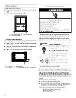
A. Cabinet louvers

A

B

C

D

E

F

G

H

I

J

A

Summary of Contents for CA15WYR0

Page 1: ...AIR CONDITIONER Use CareGuide For questions about features operation performance parts accessories or service call 1 800 253 1301 Table of Contents 2 1188226B ...

Page 2: ...ed or seriously injured if you don t follow All safety messages will tell you what the potential hazard is tell you how to reduce the chance of injury and tell you what can happen if the instructions are not followed Your safety and the safety of others are very important We have provided many important safety messages in this manual and on your appliance Always read and obey all safety messages T...

Page 3: ...ioner NOTE Do not use an extension cord Free movement of air in room to be cooled A large enough opening for the air conditioner Installation parts are supplied for double hung windows Adequate wall support for weight of air conditioner Air conditioner weighs 80 lbs 36 3 kg to 125 lbs 56 7 kg NOTE Cabinet louvers must not be obstructed Air must be able to pass freely through the cabinet louvers Fl...

Page 4: ...ocal codes and ordinances If a mating outlet is not available it is the customer s responsibility to have a properly grounded 3 prong outlet installed by a qualified electrical installer It is the customer s responsibility To contact a qualified electrical installer To assure that the electrical installation is adequate and in conformance with National Electrical Code ANSI NFPA 70 latest edition a...

Page 5: ...user serviceable parts Opening the tamper resistant case voids all warranty and performance claims INSTALLATION INSTRUCTIONS UnpacktheAirConditioner Remove packaging materials Remove and properly dispose of packaging materials Remove tape and glue residue from surfaces before turning on the air conditioner Rub a small amount of liquid dish soap over the adhesive with your fingers Wipe with warm wa...

Page 6: ...emble the tray frame insert tab on tray back into slot on tray side Check to see that the tab is engaged and the 2 pieces are aligned Insert 2 8 18 x hex head screws to secure 2 Repeat with other tray side Attach Support Legs 1 Determine the correct slots on the tray side from the type of exterior construction of the building Thin Wall Construction vinyl wood etc Thick Wall Construction brick A Tr...

Page 7: ...exterior of building can be damaged by support legs place a board between the wall and support legs 3 With tray center pushed away from the windowsill place a level on the angled edge on top of the tray side Be sure level is against notch on tray side 4 Adjust SMART MOUNT tray until bubble indicates the angled edge on top of the tray side is level IMPORTANT The tray must slope downward slightly to...

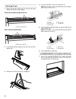
Page 8: ...w Bottom View 5 Extend right hand curtain outward so you may insert the first screw through the middle hole of the curtain Using a 8 x pan head screw screw curtain to middle hole in air conditioner cabinet NOTE This screw is required to correctly attach curtain top to bottom to the air conditioner cabinet 6 While the right hand curtain is still extended insert screws into top and bottom slots of c...

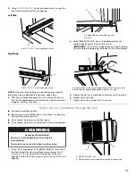
Page 9: ...If the bottom of the air conditioner does not sit against the bottom of the SMART MOUNT tray remove air conditioner and adjust angle of tray until air conditioner sits against the bottom of the tray IMPORTANT The tray must slope downward slightly toward the outside to provide proper drainage for the air conditioner Attach Side Curtains to Window 1 Pull left hand curtain frame out until it fits int...

Page 10: ...sing a wood metal or plastic molding the wood frame should line up with inside wall as shown Option 2 Plaster Wall With No Molding If the plastered wall is to be flush with the cabinet and no molding is used the wood frame must be set 13 mm into the inside wall A Side curtain against window channel B Window channel C 8 x round head screw A Lower window sash B Foam seal C A B A B A Upper window sas...

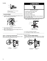
Page 11: ...he opening against the inside edge 8 Center the tray back in the opening and align it with the inside edge of the opening Using the 2 inside screw holes in the tray back mark screw locations for mounting the SMART MOUNT tray 9 Remove the tray back Using these marks drill pilot holes approximately 1 3 8 cm deep Assemble SMART MOUNT Tray 1 To assemble the tray frame insert tab on tray back into slot...

Page 12: ...just angle when installed 5 Insert second carriage bolt through tray side and attach other end of support leg NOTE Do not tighten The leg must be able to move freely to adjust angle when installed 6 Install support leg on other side Install SMART MOUNT Tray Assembly in Wall Opening 1 From inside place SMART MOUNT tray support legs facing down in the wall opening Match the holes in tray side with t...

Page 13: ...roughtheWall Handle air conditioner gently Be sure your air conditioner does not fall out of the opening during installation or removal Do not block the louvers on the front panel Do not block the louvers on the outside of the air conditioner 1 Place the air conditioner in the SMART MOUNT tray Check that feet on bottom of air conditioner are resting on the 1 9 cm x 2 5 cm wood strip at the bottom ...

Page 14: ...d slightly toward the outside to provide proper drainage for the air conditioner 5 Install screws through the top channel to secure the air conditioner into the wall opening Complete Installation 1 Trim and seal around the air conditioner on the inside and the outside NOTE Allow for removal of the air conditioner at a later time for routine annual maintenance 2 Plug into a grounded 3 prong outlet ...

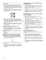
Page 15: ... display the previous settings for 3 seconds and then display the room temperature 3 Select mode See Mode 4 Select fan speed See Fan Speed 5 Set temperature See Temperature Mode 1 Press MODE until you see the indicator light come on for the setting you desire 2 Choose Auto Cool Fan Only or Power Saver Auto Cools room while it automatically controls fan speed You cannot change fan speed but you can...

Page 16: ...To set the Timer to turn on the air conditioner keeping previous settings 1 Turn off air conditioner 2 Press TIMER Timer indicator light will flash Hour indicator light will turn on and display will show remaining hours before air conditioner will turn on 3 Press the plus or minus button to change delay time 1 to 24 hours 4 Press TIMER again or wait 10 seconds Timer indicator light will remain on ...

Page 17: ...ture will decrease 1º until it reaches 64 F 18ºC NOTE After 3 seconds Set indicator light on air conditioner will turn off and Room indicator light on air conditioner will turn on Display on air conditioner will show the current room temperature To set the Timer for a 1 to 24 hour delay until the air conditioner turns off the air conditioner must be On 1 Press TIMER Timer indicator light on air co...

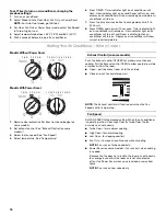
Page 18: ...Power Saver Models With Power Saver 1 Remove clear protective film from front panel badge on some models 2 Set exhaust control See Exhaust Control on some models 3 Select the fan speed See Fan Speed 4 Select temperature See Temperature Exhaust Control on some models Push the Exhaust control CLOSED for maximum continuous cooling Pull the Exhaust control OPEN to allow you to draw stale or smoky air ...

Page 19: ...e wheel to direct the air right or left Rotate the whole cartridge to direct air up down or straight ahead NormalSounds When your air conditioner is operating normally you may hear sounds such as Droplets of water hitting the condenser causing a pinging or clicking sound The water droplets help cool the condenser Air movement from the fan Clicks from the thermostat cycle Vibrations or noise due to...

Page 20: ... air filter in the dishwasher or use any chemical cleaners Air dry filter completely before replacing to ensure maximum efficiency 4 Replace air filter by sliding filter back into either side of unit CleaningtheFrontPanel 1 Turn off air conditioner 2 Remove the air filter and clean it separately See Cleaning the Air Filter 3 Wipe the front panel with a soft damp cloth 4 Air dry front panel complet...

Page 21: ...ly cord trips Reset button pops out Disturbances in your electrical current can trip Reset button will pop out the power supply cord Press and release RESET listen for click Reset button will latch and remain in to resume operation Electrical overloading overheating cord pinching or aging can trip Reset button will pop out the power supply cord After correcting the problem press and release RESET ...

Page 22: ... hot Allow extra time for the air conditioner to cool off a very hot room Windows or doors to the outside are open Close all windows and doors The Exhaust control is set to OPEN on some models Push the Exhaust control CLOSED for maximum cooling Depending on model the Temp Time or Temperature control is not at a cool enough setting Adjust the TEMP TIME control to a cooler setting by pressing the mi...

Page 23: ...ber label See Electrical Requirements for model and serial number location Please record the model and serial number information below Also record the purchase date of your appliance and the store s name address and telephone number Model Number__________________________________________________ Serial Number __________________________________________________ Purchase Date__________________________...

Page 24: ...1188226B 2005 All rights reserved SMART MOUNT is a trademark of Whirlpool U S A 12 05 Printed in U S A ...

Reviews: