


P84022 F
Sheet 4 of 6
WIRING INFORMATION:
Figure 1: Wiring Diagrams
OR END OF LINE
FROM PRECEDING
APPLIANCE, FACP
TO NEXT SIGNAL
AUDIBLE VISIBLE
AUDIBLE VISIBLE
+
-
+
-
+
-
+
-
+
-
RED
BLK
RED
BLK
STROBES
RESISTOR (EOLR)
OR SYNC MODULE
STROBE/PLATE
ASSEMBLY
AUDIBLE & VISIBLE
APPLIANCES
OPERATE
INDEPENDENTLY
STROBE/PLATE
ASSEMBLY
AUDIBLE & VISIBLE
APPLIANCES
OPERATE
IN UNISON
FROM PRECEDING
APPLIANCE, FACP
OR SYNC MODULE
FROM PRECEDING
APPLIANCE, FACP
OR SYNC MODULE
FROM PRECEDING
APPLIANCE, FACP
OR SYNC MODULE
TO NEXT
APPLIANCE
OR EOLR
TO NEXT
APPLIANCE
OR EOLR
TO NEXT
APPLIANCE
OR EOLR
Figure 2.
1) All strobe appliances have in-out wiring terminals that
accepts two #12 to 18 American Wire Gauge (AWG)
wires at each screw terminal. Strip leads 3/8 inches and
connect to screw terminals.
2) Break all in-out wire runs on supervised circuits to assure
integrity of circuit supervision as shown in Figure 2.
Strobe/Plate assembly has two red leads and two black
leads for in-out wiring. The polarity shown in the wiring
diagrams is for the operation of the appliances. The
polarity is reversed by the FACP during supervision.
Refer to Sync Module instruction sheets SM (P83123), DSM (P83177)
or PS-12/24-8 (P83862) for additional information.
MOUNTING OPTIONS:
WARNING: REMOVAL OF THE BLACK COVER AT THE BACK OF THE MOUNTING PLATE COULD RESULT IN SEVERE
ELECTRIC SHOCK.
CAUTION
:
The following figures show the maximum number of field wires (conductors) that can enter the backbox used with
each mounting option. If these limits are exceeded, there may be insufficient space in the backbox to accommodate the field wires and
stresses from the wires could damage the product.
Although the limits shown for each mounting option comply with the National Electrical Code (NEC), Wheelock recommends use of
the largest backbox option shown and the use of approved stranded field wires, whenever possible, to provide additional wiring room
for easy installation and minimum stress on the product from wiring.
FLUSH MOUNTING
A
STD. SINGLE-GANG
BACKBOX 2" DEEP
#6-32 X 5/8"
SCREWS
STROBE MOUNTING
PLATE (SMP)
BEAUTY PLATE (SUPPLIED)
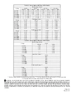
MAXIMUM NUMBER OF CONDUCTORS
AWG #18 AWG #16 AWG #14 AWG #12
4 4 4 4
FLUSH OR SURFACE MOUNT
MAXIMUM NUMBER OF CONDUCTORS
AWG #18 AWG #16 AWG #14 AWG #12
4 4 4 4
4" SQ. X 1-1/2" DEEP BACKBOX
OR 100m X 37.5mm
EUROPEAN BACKBOX
STROBE MOUNTING
PLATE (SMP)
B
#8-32 X 3/4"
SCREWS
BEAUTY PLATE (SUPPLIED)
FLUSH OR SURFACE MOUNT
C
MAXIMUM NUMBER OF CONDUCTORS
AWG #18 AWG #16 AWG #14 AWG #12
4 4 4 4
DOUBLE-GANG X 2-1/4"
DEEP BACKBOX
#6-32 X 5/8"
SCREWS
STROBE MOUNTING
PLATE (SMP)
BEAUTY PLATE (SUPPLIED)
#8-32 X 3/4"
SCREWS
D
SURFACE MOUNTING
SHALLOW SURFACE
BACKBOX (SHBB)
MAXIMUM NUMBER OF CONDUCTORS
AWG #18 AWG #16 AWG #14 AWG #12
4 4 4 4
STROBE MOUNTING
PLATE (SMP)
BEAUTY PLATE (SUPPLIED)
E
FLUSH MOUNTING
MAXIMUM NUMBER OF CONDUCTORS
AWG #18 AWG #16 AWG #14 AWG #12
8 8 8 8
STANDARD 4" X 2-1/8"
DEEP BACKBOX
APPLIANCE
SURFACE MOUNTING
MAXIMUM NUMBER OF CONDUCTORS
AWG #18 AWG #16 AWG #14 AWG #12
8 8 8 8
APPLIANCE
BACKBOX (SBL-2)
F
Figures E and F are shown with optional 6” bell. See Table 1A for other possible appliance combinations.


