


13
4.1 Entering Setup
Turn on the computer and check for the “patch" code. If there is a number
assigned to the patch code, it means that the BIOS supports your CPU. If
there is no number assigned to the patch code, please contact an Advantech
application engineer to obtain an up-to-date patch code file. This will ensure
that your CPU's system status is valid. After ensuring that you have a
number assigned to the patch code, press <DEL> and you will immediately
be allowed to enter setup.
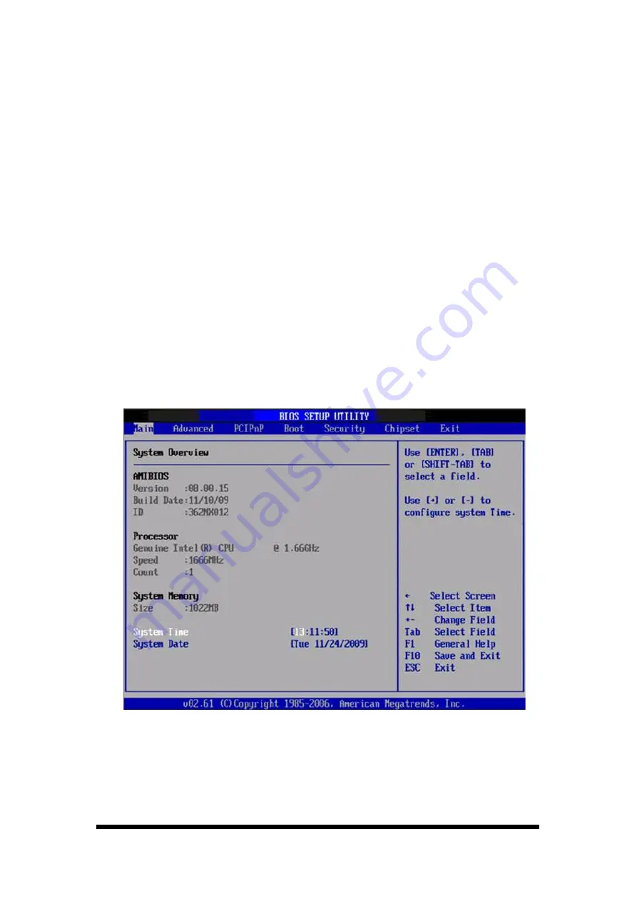
4.2 Main Setup
When you first enter the BIOS Setup Utility, you will enter the Main setup
screen. You can always return to the Main setup screen by selecting the
Main tab. There are two Main Setup options. They are described in this
section. The Main BIOS Setup screen is shown below.
Figure 4-2
Main setup screen
The Main BIOS setup screen has two main frames. The left frame displays all
the options that can be configured. Grayed-out options cannot be configured;
options in blue can. The right frame displays the key legend.
Summary of Contents for VMT12
Page 1: ...VMT12 User Manual Rugged Vehicle Mount Terminal...
Page 4: ...5 3 3 SUSI Utilities 45 5 3 4 SUSI Installation 46 5 3 5 SUSI Sample Programs 48...
Page 39: ...2 30 2 4 7 Help To tap can get help information for each program...
Page 49: ...10 3 3 2 Board Dimension Figure 3 3 Board Dimension layout Component side...
Page 50: ...11 Figure 3 4 Board Dimension layout Solder side Figure 3 5 Board Dimension layout Coastline...
Page 58: ...19 4 3 5 ACPI Settings Figure 4 8 ACPI Settings...
Page 75: ...36 4 7 Advanced Chipset Settings Figure 4 23 Advanced Chipset Settings...


