Westlab 663-958C User Manual Download Page 8

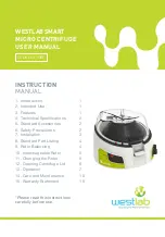
To open the centrifuge lid, 

press the “Lid Release” 

button down.

Push Down

Lid Release

Button

Correct Method

Push Down

Correct Method

Lid Release

Button

60

RPM(X100)

Min


7


13. OPERATION

TIME & SPEED SETTINGS AND DISPLAY

To operate this Micro Centrifuge, the below steps 

should be followed:
1. Connect the power adaptor & Switch ‘On’ from the

rear side so that the display will show you the fix

RPM readings.

2. Load the rotor symmetrically to avoid accidents and

damage to the centrifuge.

4. Close the lid & flip ON the front switch to start

centrifugation.

5. Once the centrifugation is completed, turn the front

switch to “Off” to gradually stop the rotor.

6. After the rotor has stopped, press the lid release

button and open the lid with your thumb in front and

fingers on the top - simply lift the lid back on the hinge.

7. If you want to stop the centrifuge quickly, push the lid

release button and the rotor will stop within a

few seconds.

In the following pages the routine centrifuge operation 

procedures are explained in brief.

WESTLAB
SMART MICRO
CENTRIFUGE

USER MANUAL

CODE  663-958

C

Summary of Contents for 663-958C

Page 1: ...nical Specifications 2 5 Standard Accessories 2 6 Safety Precautions 2 7 Installation 3 8 Standard Part Listing 4 9 Rotor Balancing 4 10 Interchageable Rotor 5 11 Changing the Rotor 5 12 Opening Centr...

Page 2: ...e on lid opening for user safety Quick start stop for short spin Smooth and quiet running Tiny footprint It can squeeze easily on to a crowded counter top Interchangeable PCR rotor adaptor Low voltage...

Page 3: ...4 C to 45 C Main supply voltage fluctuations not to exceed 10 of the nominal voltage Position at least 20 cm from walls 20 cm from ceiling and 20 cm between other products Make sure to always install...

Page 4: ...ied micro centrifuge tubes made from plastic and designed to withstand centrifugal forces of at least 2000 g Do not operate the centrifuge without the rotor being properly attached to the shaft Re che...

Page 5: ...e serious damage to the centrifuge 8 STANDARD PARTS LISTING ON OFF SWITCH NON SLIP RUBBER BASE POWER SOCKET PROTECTIVE LID ROTOR SAFETY SWITCH DISPLAY RELEASE BUTTON SPEED KNOB x 100RPM Min 60 TIMER K...

Page 6: ...is located at the bottom of the rotor on the marked side To remove the rotor turn counter clockwise to loosen the screw and then gently pull the rotor up vertically Insert the new rotor from the top...

Page 7: ...ter clockwise direction Trying to open the centrifuge lid by pulling the Lid Release button up is the wrong method of opening the lid Pulling the Lid Release button up will break the button or damage...

Page 8: ...id accidents and damage to the centrifuge 4 Close the lid flip ON the front switch to start centrifugation 5 Once the centrifugation is completed turn the front switch to Off to gradually stop the rot...

Page 9: ...nd rotor the actual RCF value will vary One can refer to the table mentioned in the section 7 to get the actual RCF of different rotors at certain given speed values 8 The unit is equipped with a 0 25...

Page 10: ...ge to the centrifuge This centrifuge has an unique patented feature to protect the centrifuge its user the surroundings against such as accidental run When such an event occurs the sensor build inside...

Page 11: ...us materials occur within the rotor or rotor chamber the unit should be disinfected This should be performed by qualified personnel with proper protective equipment Do not use any cleaning or decontam...

Page 12: ...turned for service should be sent with postage prepaid in the original packaging or other suitable packaging padded to avoid damage We will not be responsible for damage incurred by improper packaging...

Reviews: