


WHL-052 Rev. 4.28.16
27
Friction Loss Equivalent in Piping and Fittings
Fittings or Piping
Equivalent Feet
3”
4”
6”
90 Degree Elbow*
5’
3’
3’
45 Degree Elbow
3’
3’
2’
Coupling
0’
0’
0’
Air Inlet Tee
0’
0’
0’
Straight Pipe
1’
1’
1’
Concentric Kit
3’
N/A
N/A
V Series Vent Kit
1’
1’
1’
AL20 4c Vent Terminal
1’
1’
1’
Table 10 - *Friction loss for long radius elbow is 1 foot less. NOTE:
Consult Polypropylene venting instructions for friction loss and
pressure drop equivalents.
b. For example: If the exhaust vent is 3” in diameter, has
two 90
o
elbows, and 10 feet of PVC pipe we will calculate:
Exhaust Vent Equivalent Length = (2x5) + 10 = 20 feet.
Further, if the 3” intake pipe has two 90
o
elbows, one 45
o
elbow, and 10 feet of PVC pipe, the following calculation
applies:
Intake Pipe Equivalent Length = (2x5) + 3 + 10 = 23 feet.
The total equivalent length is 43 feet, well below the
maximum of 200 feet.
c. Effort should be made to keep a minimum difference in
equivalent length between the exhaust vent and intake
pipe.
3. The minimum total equivalent length is 16 feet.
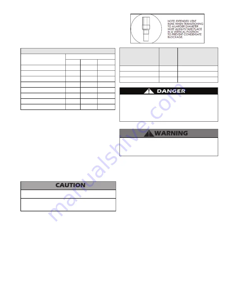
F. Longer Vent Runs
The maximum total equivalent length can be extended
by increasing the diameter of both the exhaust vent and
intake pipes equally. However, the transitions should begin
a minimum of 16 equivalent feet from the boiler. Transitions
should always be made in vertical sections of pipe to prevent
the condensate from pooling in the vent pipe.
The maximum equivalent length for increased diameter vent
pipes is 275 ft, which includes 16 ft from with boiler with a
transition total of 259 ft upsize piping for longer vent runs.
Standard
Vent Connection and
Maximum Total
Equivalent Length
Reducing
Coupling
Increased Vent Size
and Maximum Total
Equivalent Length
3” (200’)
4” x 3”
4” (275’)
4” (200’)
6” x 4”
6” (275’)
6” (200’)
8” x 6”
8” (275’)
Table 11 - Vent Run Transition
Do not exceed the maximum lengths for vent pipes. Excessive
length could result in boiler shutdown and property damage.
G. Exhaust Vent and Intake Pipe Installation
All joints of positive pressure vent systems must be sealed
completely to prevent leakage of flue products into the living
space. Failure to do so could result in property damage, serious
injury, or death.
1. Use only solid PVC, CPVC, or stainless steel pipe or a
Polypropylene vent system approved for use with Category IV
appliances.
FOAM CORE PIPING IS NOT APPROVED FOR EXHAUST VENT
APPLICATIONS. Foam core piping may be used on air inlet
piping
only
.
2. Remove all burrs and debris from joints and fittings.
3. When using PVC or CPVC pipe, all joints must be properly
cleaned, primed, and cemented. Use only cement and primer
approved for use with the pipe material. Cement must conform
to ASTM D2564 for PVC and ASTM F493 for CPVC pipe.
NOTE:
DO NOT CEMENT POLYPROPYLENE PIPE.
4. Ensure the vent is located where it will not be exposed to
prevailing winds.
5. In all roof venting applications, exhaust discharge must point
away from the pitch of the roof.
6. If the exhaust vent is to be terminated in a walled off area
(such as a roof with a parapet wall), ensure the exhaust vent
terminates a minimum of 10’ from nearest wall and extends level
with or above the top of the wall. This will ensure flue gas does
does not get trapped and possibly recirculated into the intake air
pipe, which could contaminate the combustion air.
7. To prevent water leakage, install adequate roof flashing where
the pipe enters the roof.
8. Do not locate vent over public walkways, driveways, or
parking lots. Condensate could drip and freeze, resulting in a slip
hazard or damage to vehicles and machinery.
9. Due to potential moisture build-up, sidewall venting may not
Failure to provide a minimum total vent length of 16
equivalent feet could result in property damage and improper
product operation.
E. Exhaust Vent and Intake Pipe Sizing
1. The exhaust vent and intake pipe size is 3” for 80 - 220 mod-
els and 4” for 299 - 399 models.
2. The maximum total equivalent length of exhaust vent and
intake pipe
should not exceed 200 feet
.
a. The equivalent length of elbows, tees, and other fittings
are listed in the Friction Loss Table.
Total maximum equivalent length of increased diameter exhaust
vent and intake pipe must not exceed the lengths defined in this
manual. Failure to keep the total equivalent length below the
maximum lengths determined in this manual will result in faulty
boiler operation, substantial property damage, serious personal
injury, or death.
Figure 12 - Extended Vent Runs
Summary of Contents for WBRE110
Page 13: ...WHL 052 Rev 4 28 16 13 Figure 5 Boiler Dimensions NOTE All Dimensions Are Approximate ...
Page 37: ...WHL 052 Rev 4 28 16 37 Figure 25 Internal Connection Diagram ...
Page 62: ...WHL 052 Rev 4 28 16 62 Figure 30 Combustion System Replacement Parts 80 220kBTU Models ...
Page 63: ...WHL 052 Rev 4 28 16 63 Figure 31 Combustion System Replacement Parts 299 399kBTU Models ...
Page 64: ...WHL 052 Rev 4 28 16 64 Figure 32 Cabinet Replacement Parts All Models ...
Page 65: ...WHL 052 Rev 4 28 16 65 Figure 33 Cabinet Replacement Parts All Models ...