background image

1\) 

0) 

� 

.... 

!'> 

� 

Cb 

� 

() 

(I) 

(') 

:r 

<D 

Ill 

g. 

... 

(I) 

OJ 

7' 

.... 

::0 

<D 

ii> 

':"= 

tSPP 

.... 

� 

0) 

� 

() 

Qj 

62-1 

I

SPPt 

62-1 

""15 

X(L)SEAL  IN 

DC  NEG 

Is 

II 

WHEN 

USED 

DC  POS 

62-1 

II 

AR 

R ED 

!

X(R )  

62-1 
12 

TO  R ETR IP 

BR EAKER  52-I 

(TO OBTAIN  AR 

CONTACT  OUTPUT 

MOVE  R ED  LEAD 
F R OM  TER MINAL  II 

TO  TER MINAL 12) 

DC  NEG 

62-1 

62-1 

8 68 F l 

ICS 

( R ) 

R EQUIR ED  WHER E  PR OTECTED 

BR EAKER  ISOLATES  A  TR ANSFOR MER 

t

e6TI 

-

____  _j 

t62-l 

13 

AR 

It� 

���� 

62-1 

14 

� 

FOR  HIGH  SPEED  T R IP 

ADJACENT  BR EAKER S 

OR 

OTHER  AUX FUNCTIONS 

R A  

ZA 

LEGEND 

DEV 

DESCR IPTION 

52 

CIR CUIT 

BR EAKER 

62 

SBF-1  BR EAKER  FAILUR E R ELAY(7nBBI3,1326DI

9 )  

62Xp2 Y  BR EAKER  FAIL UR E  INITIATE  CONTACTS 

8 6BF 

BR EAKER  FAILUR E  LOCKOUT  R ELAY 

8 6TI 

TR ANSFOR MER  LOCKOUT  R ELAY 

T Y PICAL  8 6BF  AND

/

OR 

R E L AY  AUX  F UNCTIONS 

I. T R IP  BR EAKER S  CONNECTED  TO SAME  BUS  SECTION 

2.BLOCK  ALL  AUTOMATIC  R ECLOSING. 

3.BLOCK  MANUAL  CLOSING-

4.KEY  TR ANSFER  TR IP  TR ANSMIT TER S  TO  TR IP 

R EMOTE  BR EAKER S  AND  BLOCK  R ECLOSlNG. 

5 .  STOP"  BLOCKING"  CAR R IER . 

SPP  SUR GE  PR OTECTION  CAPACITOR  TO  BE  USED 

WHEN  SUR GE  VOLTAGE  MAY  EXCEED 25 00VOLTS  PEAK 

':f=  WHEN SUR GE  VOLTAGE  MAY  EXCEED  2 5 0 0VOLTS PEAK 

USE  SHIELDED  CONTR OL  CABLE 

GR OUND  BOTH ENOS 

PER  SWITCH YAR D  R UNS  WHER E  SUR GE  VOL TAGE MAY 

EXCEED  2500  VOLTS  R EAR 

AC  SCHEMATIC 1464C77 

www 

. ElectricalPartManuals 

. com 

Summary of Contents for SBF-1

Page 1: ...tapped and brought out to a tap block located on the front of the relay Each transformer has three taps which cover the range of pickup The secondary of the transformers are con nected to the input o...

Page 2: ...as well as the X seal in relay is reset after it times out The circuit operation can be explained by referring to the internal schematic drawing 77588 1 3 Fig 2 and detailed internal schematic 1 3260...

Page 3: ...ained by using a current source and a precision ammeter CAUTION Since the tap block connector screw carries operating current be sure that the screw is turned tight In order to avoid opening the curre...

Page 4: ...rrent unit is obtained by means of a tap screw and tap block in conjunc tion with the tap multiplier knob setting located at the front of the overcurrent unit module This per mits a continuous adjustm...

Page 5: ...ch or equivalent use the 0 2 amp tap For 48 Vdc applications set the unit in the 2 amp I L 41 776 5 t a p and use a type WL relay with a S 304C209G01 coil or equivalent I NSTALLATION The relays should...

Page 6: ...low state in 1 90 to 210 milliseconds If some other time interval is desired the timer setting may be changed by means of a screw driver adjustment through the access hole on the timer 6 module to a m...

Page 7: ...t point TP6 and TP7 on the timer board Energize the relay with rated de voltage and apply 0 48 Amps ac current to phase A With the tap in the 0 5 position and the phase multiplier dial knob fully coun...

Page 8: ...cation of trouble in service or dur ing routine checks the following information will prove helpful All measurements are approximate and may vary as much as 20 All voltages are positive with reference...

Page 9: ...voltage at terminal 4 should measure 6 4V The voltage at printed circuit board I L 41 776 5 terminal 3 should measure 23 5Vdc before the output relay operates and less than 2 5V after it operates 3 J...

Page 10: ...Current 4 5A S OA VA 23 28 OHMS 0 1 1 01 1 P F Angle 36 1 8 Saturated Burden Current Lagging Voltage CLOSED 4 5A S OA 16 20 008 008 5 4 OPEN C LOSED SA SA O SA S OA 53 2 1 33 2 2 23 08 1 5 09 63 25 20...

Page 11: ...5 TABLE 4 I L 41 776 5 0 5 to 1 3 5 Amperes 1 SECOND 250 Amps 250 300 AR CONTACT RATINGS I NTERRUPTING RATING CONTACT CIRCUIT TRIP CARRY RATING RESISTIVE I NDUCTIVE RATING RATING CONTINUOUS L R 005 4...

Page 12: ...ER TB TRANSFORMER TA Fig 1 Photograph of SBF 1 Relay without case with four overcurrent input Front view 12 SEAL IN RELAY X ICS INDICATING CONTACTOR SWITCH w w w E l e c t r i c a l P a r t M a n u a...

Page 13: ...right oblique I L 41 776 5 POTENTIOMETER PA POTENTIOMETER PC POTENTIOMETER PG POTENTIOMETER PB TRANSFORMER TG RESISTOR RS 1 3 w w w E l e c t r i c a l P a r t M a n u a l s c o m...

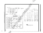
Page 14: ...MOVE RED LEAD FROM TERMINAL II TO TERMINAL 12 L R LC S RC DENOTE LEFT HAND RIGHT HAND LEFT CENTER S RIGHT CENTER POSITIONS REF DWG 25W RESISTORS 1326DI9 DETAILED SCHEMATIC 1326D31 4 OVERCURRENT UNITS...

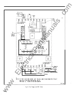
Page 15: ...TED VDC 13 FROM TERM 3 OF 4 OVERCURRENT DETECTOR MODULE RATED VDC 3 52 a TIMER AND O UTPUT MODULE 4 PI IS PANEL MOUNTED 17 7 L TO X RELAY 10 J WHEN USED REPLACED BY FOR GROUPS I Fig 4 Internal SCR w w...

Page 16: ...RIPTI JN STYLE N0 JUM P R 0 OHM RESISTOR 862A413HO I Jl DESCRIPTI J J STYLE POT 20 0K 501 1 862A406H02 P2 25 0K sow SSOA687H02 PI DESCRIPTHlN STYLE TRANS STOR 2N2905A 762A672H O 01 2 lt 7 1 1 762A585H...

Page 17: ...Pl 2 a Pl 3 I 14 Fig 5 Component Location tor Timer Module 48 or 125Vdc rated relay I L 41 776 5 3517A76 19 w w w E l e c t r i c a l P a r t M a n u a l s c o m...

Page 18: ...WHEN USED 3517A77 Fig 6 Com u e 250Vdc rated relay ponent Location for Timer Mod I 20 w w w E l e c t r i c a l P a r t M a n u a l s c o m...

Page 19: ...o z uot s I d SH U7H7 ki 0 12 lJ SCKIPfiJ TYLI ZE EK 1 751A f 2 J r r n r o1 Z2 1 17j21 JJ Jv 0 I I d c Zl DESCRIPTltlN STYLE NG I POT 500 0 2 00W 10 7o 848A778H04 PA PC PG IO OK 12 5W O lo 836A635HI...

Page 20: ...3517A78 Fig 8 Component Location for 3 Current Input Overcurrent Detector Module 22 w w w E l e c t r i c a l P a r t M a n u a l s c o m...

Page 21: ...I L 41 776 5 3517A79 Fig 9 Component Location for 4 Current Input Overcurrent Detector Module 23 w w w E l e c t r i c a l P a r t M a n u a l s c o m...

Page 22: ...G X TAP MULTIPLIER r l I TO RH CONTACT OF AR RELAY I t L _ Q J_ 2 4 s a lGND J l L J TO RH CONTACT I OF AR RELAY I l l 9 Qg _j LO BOUNCE SWITCH TO TESTTIMER RATED START VDC TO TESTTIMER COMMON NOTE TO...

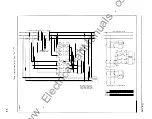
Page 23: ...PPt 62 l 62 l 2 _ _3 r 1 IB WHEN 62 1 16 USED 17 r n 6 Ic f 1 _ Io 6 1 f Jf 1 SPP t rv r rv P J SBF 1 RELAY FOR BREAKER 52 2 r r BACKUP r RELAYS r r JPRIMAR t SPP SURGE PROTECTION CAPACITORS TO BE USE...

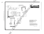
Page 24: ...BR EAKER FAILUR E R ELAY 7nBBI3 1326DI 9 62Xp2 Y BR EAKER FAIL UR E INITIATE CONTACTS 8 6BF BR EAKER FAILUR E LOCKOUT R ELAY 8 6TI TR ANSFOR MER LOCKOUT R ELAY T YPICAL 8 6BF AND OR R E L AY AUX F UNC...

Page 25: ...EXTERNAL TOOTHED WASHERS 4 375 1 1 1 1 3 1 90 32 SCREW 4 375 SPACERS FOR I l l 1 3 THIN PANELS I L 41 776 5 5 5631 250 DIA 4 HOLES FOR 141 30 6 35 190 32 MTG SCREWS f 1 5707903 Fig 13 Outline and Dri...

Page 26: ...w w w E l e c t r i c a l P a r t M a n u a l s c o m...

Page 27: ...w w w E l e c t r i c a l P a r t M a n u a l s c o m...

Page 28: ...W E S T I N G H O U S E E L E C T R I C C O R P O R A T I O N R E LAY I NST RU M E NT D IVISION CORAL SPRI NGS F L Printed in U S A w w w E l e c t r i c a l P a r t M a n u a l s c o m...

Page 29: ...tap block located on the front of the relay Each transformer has three taps which cover the range of pickup The secondary of the transformers are con nected to the input of the plug in detector modul...

Page 30: ...ctor The breaker failure timer controls the fault detector so that after it times out the overcurrent signal if present is connected to the level detector This arrangement keeps the overcurrent input...

Page 31: ...rent is reduced to zero or up to 95 of pickup current Continuous rating is 1 0 amperes One second rating is 250 amperes The accuracy of the pickup setting is 5 over the full range and 10 from 20 to 55...

Page 32: ...cts will safely close 30 amperes at 250 Vdc and the seal in contacts of the ICS will safely carry this current long enough to trip a cir cuit breaker SETTINGS OVERCURRENT DETECTOR The pickup of the ov...

Page 33: ...41 776 5A resistor that is inserted on tripping and the over current fault detectors are set below the resistor current the additional time for this interruption must be included A secure margin for...

Page 34: ...e will speed up the dropout time longer range timer Use the same test with applying current to BREAKER FAILURE BF i f phase C and also phase B if used Pickup should TIMER be within 5 of the phase A pi...

Page 35: ...e relay if the relay has been taken apart for repairs or the adjustments have been disturbed This procedure should not be used unless it is apparent that the relay is not in proper working order Overc...

Page 36: ...ee that the contacts close at rated tap value current The indicating target should drop at or just prior to the contacts closing The targer should drop freely I f the target does not drop or does not...

Page 37: ...1 posi tion I L 41 776 5A a With 0 4 amp ac current flowing apply rated relay voltage Measure voltage at terminal 5 of I C I to be 6 4V Now increase the current until the output relay operates The vo...

Page 38: ...OA VA 1 65 75 06 60 63 75 50 60 O H M S 073 03 027 024 03 1 03 024 024 P F Angle 45 36 1 5 1 5 36 36 1 5 1 5 TAP 4 5 TAP MULT 1 4 5A PICKUP 3 1 3 5A PICKUP REED RR CONTACT OPEN CLOSED OPEN C LOSED Cu...

Page 39: ...T RATINGS I L 41 776 5A I NTERRUPTING RATING CONTACT CIRCUIT TRIP CARRY RATING RESISTIVE I NDUCTIVE RATING RATING CONTINUOUS L R 005 48Vdc 30 Amps 3 Amps 3 75 Amps 1 75 Amps 1 25 30 3 5 35 250 30 3 25...

Page 40: ...ER TB TRANSFORMER TA Fig 1 Photograph of SBF 1 Relay without case with four overcurrent input Front view 12 SEAL IN RELAY X ICS INDICATING CONTACTOR SWITCH w w w E l e c t r i c a l P a r t M a n u a...

Page 41: ...right oblique I L 41 776 5A POTENTIOMETER PA POTENT OMETER PC POTENTI OMETER PG _ _ POTENTIOMETER PB TRANSFORMER TG RESISTOR RS 1 3 w w w E l e c t r i c a l P a r t M a n u a l s c o m...

Page 42: ...R l L Cl RCl DENOTE LEFT HANO RIGHT HAND LEFT CENTER a RIGHT CENTER POSITIONS W RESISTORS VOLTS DC RA RS 1326DI9 DET AILED SCHEMATIC 48 900 n 200 n 1326D31 4 OVERCURRENT UNITS WIRING 1 326 D83 3 OVERC...

Page 43: ...13 FROM TERM 3 OF 4 OVERCURRENT DETECTOR MODULE RATED VDC 52 a f i 4 TIMER AND OUTPUT MODULE PI IS PAN E L MOUNTED 7 TO X RELAY 10 WHEN USED I I I I 9 I I I REPLACED BY J FOR GROUPS I a 0 Fig 4 Intern...

Page 44: ...UZ8 70 Q Q IJ 0 37 A 69 JH I 4 matic of Timer Module 1454C81 G02 125 VDC 1454C81 G03 2 50 VOC CAPAC T O R C J C2 Cl D H l U D l 2 03 II A DX l N T CKT I C I JUMPER J l 2 P2 P I P0T TRtu I S I S H J R...

Page 45: ...Pl 2 a Pl 3 I 14 Fig 5 Component Location for Timer Module 48 or 125Vdc rated relay I L 41 776 5A 3517A76 19 w w w E l e c t r i c a l P a r t M a n u a l s c o m...

Page 46: ...20 Fig 6 Comp anent Location for Timer Mod I u e 250Vdc rated relay WHEN USED 3517A77 w w w E l e c t r i c a l P a r t M a n u a l s c o m...

Page 47: ...l 7 J J Q j Q Q 5 1 7 rl 6 J J 5 R l 5 0 0 00 5 7 6 ll 1 7Yll R l 2 4 5 J Q Q 1 57 J tl 7 A 6 4 3rlJ R l 6 3 9 2 00 o 5 4 6 5A 2 J 7 L l 1 1 3 1 4 J O Q Q 2 00 1t 5 4 J 5f 2 0 7 H 7 5 R9 10 12 UESCRJ...

Page 48: ...3517A78 Fig 8 Component Location for 3 Current Input Overcurrent Detector Module 2 2 w w w E l e c t r i c a l P a r t M a n u a l s c o m...

Page 49: ...I L 41 776 5A 3517A79 Fig 9 Component Location for 4 Current Input Overcurrent Detector Module 23 w w w E l e c t r i c a l P a r t M a n u a l s c o m...

Page 50: ...I TO RH CONTACT TO RH CONTACT I OF AR RELAY OF AR RELAY I I 1 l i L _ C0_ 2 4 6 l 9 _j L g uc N HCE f JA1 l c1 lGND IOK TO TESTTIMER RATED Y Y f START VDC TOTESTTlMER COMMON NOTE TO TEST FOR OVERCURR...

Page 51: ...62 2 r SBF I RELAY FOR BREAKER 52 2 rrll l rr x 6 llf f 1 1 1 1 1 l f 6 lc 62 I BACKUP f A vT RELAYS r t 62 1 Io L 7 fs t f I P E t SPP SURGE PROTECTION CAPACITORS TO BE USED WHEN SURGE VOLTAGE MAY E...

Page 52: ...D ________ _____ I u I CIRCUIT BR IPTION S8F IBREA ERFAILUR R lAY 775 1326 D 1 9 2X 62Y BREAKER FAI L U R E I N I T IAT CO _ N _ TACTS l LBSBF BREA K E R FAILURE LOCKOUT RELAY 86TI TRANSFOR M E R LOC...

Page 53: ...750 400 05 5 875 149 23 2 938 74 63 PA NEL C U TOUT 8t DR I L L I N G FOR S E M I FLU S H MTG LARGE INT E R N I 5 5 6 a E XT E RNA L _L_ J t TOOTH WASHER r 64 1 16 2 8 S M A LL EXTERNAL TOOTHED WASHER...

Page 54: ...w w w E l e c t r i c a l P a r t M a n u a l s c o m...

Page 55: ...w w w E l e c t r i c a l P a r t M a n u a l s c o m...

Page 56: ...W E S T I N G H O U S E E L E C T R I C C O R P O R A T I O N R E LAY I N ST R U M E NT DIVISION CORAL S P R I N G S FL Printed in U S A w w w E l e c t r i c a l P a r t M a n u a l s c o m...

Reviews: