background image

:

OPERATING  MECHANISM 

The  operating  mechanism  (see  Fig.  5) 

is 

non­

adjustable  and  consists  of  a series of steel  links  de­
signed  to  secure  low  closing  and  tripping  forces. 
To  check  for  friction,  raise  the  trip  bar  and  slowly 

rotate  the  manual  operating  handle  in  close  and 
trip direction.  The linkage should follow the handle 
without sticking. 

The  tripping  load  should  not  exceed 

38 

ounces 

measured  at  the trip  bar. 

CLOSING  SPRING  ASSEMBLY 

The  closing  spring  assembly  is  shown  in  the 

·breaker  closed  position  in  Fig.  5.  Assuming  the 

breaker is in the open position, the following closing 
sequence applies: 

- Rotating  the  closing  handle  clockwise  raises  the 

lift 

link  and  lower  spring  guide  to  compress  the 

closing  spring.  Near  the  end  of  the  closing  stroke 

the  top  end  of  the  lift  link  strikes  the  first  toggle 

lever  to  start  the  breaker  closing.  As  the  breaker 
closes the  push rod raises the toggle link and  push 
link  out  of  toggle which  permits  the closing spring 

..... ·.  ·' 

� 

to complete the breaker  closing. 

FIG. 

6. 

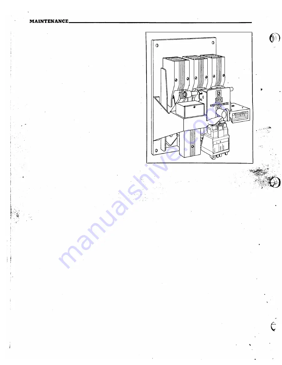
Overcurrent  Tripping  Device-Location 

<.' 

... 

Slow  emergency  operation  to  check  th�  contact 

... 

· 

sequence  can  be  obtained  by  exerting  a  slight  .  signed 

for 

service  Qn 

motor 

or  gener

<l:!_

·'

ll.rpos� 

closing  pressure  on  the  closing  handle  and  simul-

feeder  circuits  or  for  service  on  systems 'where 

·  · 

taneously  pushing  forward  on  the  bre'aker  cross 

selective  overcurrent  tripping 

is 

desired. 

Figures 

·" 

bar to start fhe breaker closing. 

-�"c.7A 

and  7B  shows  time-current  characteristics  of 

Maintenance. 

Oil  the  pins  and  slides  every 

DB-15  and  DB-25,  circuit  breakers  equipped  with 

lO,QOO 

operations. 

typical  overcurrent  tripping  devices,  for  selective 
tripping. 

CLOSING  SOLENOID 

The closing solenoid (see Fig. 

5) 

is non-adjustable. 

It is designed  for intermittent duty  only.  Check for 
loose bolts. 

The minimum permissible  control  voltages  at the 

terminal of the closing coil, and the closing currents 

at nominal voltage are listed in Table No.2 on page 12. 

OVERCURRENT  TRIPPING  DEVICE 

The  overcurrent  tripping  devices  of  the  various 

ampere ratings are of the same general construction 
and  size.  They  can  be  applied  to  the  DB-15  circuit 

breaker in  ratings  of  15  to  225  amperes  and  to the 
DB-25  circuit  breaker  in  ratings  of 

40 

to 

600 

amperes. 

The  overcurrent  tripping  device  can  �asily  be 

removed from the breaker and replaced with another 

unit  of  different  rating  without  affecting  the  cali­
bration. 

The  overcurrent  tripping  device,  normally  fur­

nished  for  each  pole  of  the  circuit  breaker,  is  de-

14 

Construction. 

The overcurrent tripping device 

is  of  the  air  delayed  type  with  all  elements  adjust­
able.  The  adjustment  knobs  or  parts  likely  to  be 
touched while making adjustments of time or pic�up 
current  are  electrically  insulated.  Fig.  6A  shows 
a  typical  overcurrent  tripping  device  ready  for 

mounting on .a breaker  pole unit. 

· 

Loosening or removal  of the  reset  valve  requires 

recalibration of  the long delay scale. 

Installation and Removal. 

To install an over­

current  tripping  device,  first  make  sure  the  lower 
end  of  the  flexible  conductor  is  in  the  recessed 
pocket  of  the molded base directly  above the  lower 

breaker  stud.  Then  place  the  trip  unit  so  that the 
top  terminal  of  the  tripping  device  is  over  the 
flexible  conductor  and  the  lower  tripping  device 
terminal  is  over  the  lower  breaker  stud.  Insert  the 
three  bolts  into  the  rear  of  the  base  and  thread 
them  tightly  into  the  terminals  and  molded  base  of 
the  tripping  device.  The  mounting  bolt  sizes  are 
shown  in  Table  No. 

3. 

www 

. ElectricalPartManuals 

. com 

Summary of Contents for De-ion DB-15

Page 1: ...akers Types 08 15 08 25 DB F DBL 25 600 Volts A C 250 Volts D C Westinghouse Electric Corporation Switchgear Division East Pittsburgh Pa I B 33 850 1 2E Effective May 1965 Supersedes issue September 1963 w w w E l e c t r i c a l P a r t M a n u a l s c o m ...

Page 2: ...ce 14 Construction 14 Installation and Removal 15 Time Current Classification 21 Operation 21 Adjustment of Settings 21 Replacing Overcurrent Devices 21 Control Relay 24 Shunt Trip Attachment 24 Undervoltage Trip Attachment 24 Undervo1tage Time Delay Attachment 27 Reverse Current Trip Attachment for 2 P D C Breaker 27 Field Discharge Switch 29 Auxiliary Switch 30 Alarm Switch Attachment 30 Electri...

Page 3: ...urrent Series Tripping Device DB 15 and DB 25 Load Circuit Breakers 7D Schematic Diagram Dual Overcurrent Series Tripping Device DB 15 and DB 25 Group or Tie Circuit Breakers 8 Typical Wiring Diagrams Type DB Circuit Breaker 9 Control nelay Location Adjustment and Construction Details 10 Shunt Trip Attachment Location and Construction Details 11 Undervoltage Trip Attachment Location and Constructi...

Page 4: ... in an enclosure suitable to local operating conditions A selection of standard enclosures is available for various applications Important To assure proper functioning inspect each breaker at reg11lar intervals in accordance with a systematic maintenance schedule The frequency and character of the inspections will for the most part be deter mined by the severity of the duty performed The minimum r...

Page 5: ...Y SWITCH PLA TFO RM rwt CONTROL 1 R EL A Y A RC CHUTE 0 I B 33 850 1 2E DB AIR CIRCUIT BREAKERS SHUNT _TRIP PLATE FIG 1 Type DB Air Circuit Breaker Ez jded View 5 w w w E l e c t r i c a l P a r t M a n u a l s c o m ...

Page 6: ... handle slowly in a clockwise direction to move the contacts toward the closed position 6 a Observe whether all parts are in proper alignment and move freely b Make certain that the studs have not been forced put of alignment c Be sure that the contacts are clean and properly aligned For a description of contact align ment refer to Contacts page 12 3 If the contacts are in alignment and all parts ...

Page 7: ...sed for all other enclosures except subway and explosion proof The mounting dimensions differ for these and should be obtained from the appropriate outline drawing The following procedure applies to all enclosures 1 Connect the entrance cables first Whenever possible the power cables should be connected to the top terminals to remove voltage from the over current attachments when the breaker is op...

Page 8: ... WEJ T R PROOF DUST TIGHT WAT R TIGHT NCLOSURESONI Yo r I I I I I I I I I I 1 I I I I I i I I I I I I I I I I I I I d I I I I LJ 4__ t 21 28 1 VtN t ltiC 7 75 X 3 62 CONDUIT OPENING WITH DRILL PLATE TOP BOTTOM TO 8 DRILLED BY CUSTOMCR FIG 2 DB 15 DB 25 and DBF 6 Ventilated Enclosures Outline Dimensions and Mounting Details w w w E l e c t r i c a l P a r t M a n u a l s c o m ...

Page 9: ...8 CUTOUT IN DEAD FRONT DOOR OR COVER 0 I 0 l B KR c J c J cp c J 0 0 VIEW c FRONT VIEW OF STUD LOCATION CUTOUT a DRILLING FOR MOUNT ING 2 POLE BREAKER WITH 2 OVERCURRENT TRIPS 8 REVERSE CURRENT TRIP FOR DIMS SEE VIEW A DIA Ll 1 J It STUD 20 HANDLE I 3 3 f Ol E BREAKER WITHOUT REVERSE CURRENT TRIP OR 2 POLE BREAKER WITH OR WITHOU T liEVERSE CURRENT TRIP 7 r fo 118 24 VIEW E BOUNDA R Y SURFACES OF T...

Page 10: ...INCREASING OVERALL DIM S I AUXILIARY SWITCHES 8 CIRCUIT MAXIMUM 2 UNDERVOLTAGE TRIP 3 OPERATI ON COUNTER 4 ALARM SWITCH 5 ELECTRIC LOCKOUT 6 SHUNT TRIP PO TION INDICATOR MAX POSITION OF INTERLOCK PIN _ 1 I 4 POINT AUX SW CONTROL RELAY OVERCURRENT TRIP REVERSE CURRENT TRIP HAND TRIP AND PROVISION FOR PADLOCKING BKR II IN TRIPPED POSITION PADLOCK FURNISHED BY CUSTOMER 20 CLOSING HANDLE FOR MOVABLE I...

Page 11: ...REAKER WITH 2 OR3 OVERCURRENT TRIP S OR 2 POLE BREAKER WITHOUT REVERSE CURRENT TRIP FRONT VIEW OF STUDLOCATION CUTOUT B DRILLING FOR MOUNTING 2 POLE BREAKER WITH 2 OVERGURRENT TRIPS B REVERSE CURRENT TRIP 3 POLE BREAKER WITHOUT REVERSE CURRENT TRIP OR 2 POLE BREAKER WITH OR WITHOUT REVEP SE CURRENT TRIP 17 8 4 L HANDLE lFOR DIMS SEE VIEW A l VIEW E BOUNDARY SURFACES OF THE CIRCUIT BREAKER ARE TO B...

Page 12: ...d position It should be possible to obtain at least Awinch gap between contacts Maintenance of Contacts Rough or high spots should be removed with a file or sandpaper To replace the arcing contacts open the breaker remove the arc chutes and then the stationary arc ing contacts Close the breaker and remove the moving arcing contacts The new contacts can then be added in the reverse order Caution Al...

Page 13: ...NG COil 216 CLOSED DB 25 CIRCUIT BREAKER 600 AMPERES 600 VOLTS PAWL 232 STATAIONARY ARCING CONTAC T 219 OVERCURRENT TRIPPING DEVICE 217 e i oJ o __ TRIPPED FIG 5 Cross Sectional View o Type DB 25 Circuit Breaker 13 w w w E l e c t r i c a l P a r t M a n u a l s c o m ...

Page 14: ...NG SOLENOID The closing solenoid seeFig 5 is non adjustable It is designed for intermittent duty only Check for loose bolts The minimum permissible control voltages at the terminal of the closing coil and the closing currents at nominal voltage are listedin Table No 2on page12 OVERCURRENT TRIPPING DEVICE The overcurrent tripping devices of the various ampere ratings are of the same general constru...

Page 15: ... to operate easily Then insert the push rod A Fig 6A in the top slot of the calibration bracket and push the armature solidly against the 1 yoke close the breaker and adjust the trip nut to 1 1 OVERCURRENT TRIPPING DEVICE 1 600 AMP 60 CY 0 5 164 823 DELA P CKU ERES SECONDS AT 3CCO oP5 LONS D I INJf I 1 o 0 600 z I 1 o co 10 euo 1200 LONGER I lJ eoi HIGHER SCALEPLATE 131 PIN ___ 136 LONG DELAY PICK...

Page 16: ...R DATA Standards 1 Tests made at Volts a c aL 20 v i 30 40 50 60 708090 0 0 0 0 0 0 00 0 0 0 0 0000 0 0 CURREN Percent o Coil Rating IY _TIME CURRENT CHARACTERISTIC CURVES lestinghouse Elec Corp o Fuse Links In East Pittsburgh Pa o Dated p f Starting at 25C with no initial load 2 Curves are plotted to _ _ _ _ _ _ Test points so variations should be I No 40 5123 Da e J ero e Sandin 4 29 54 04 03 02...

Page 17: ...1W OJ TIE 1iiiEM EiiS I Tests made aL ___ Volts a c nL TIME CURRENT CHARACTERISTIC CURVES Westinehouse Elect Corp Fuse Link ln Fast Pittsburgh Pa Dated_ p f Starting at 25C with no initial load 2 Curves are plotted to _ Test points so variations should be I No 405133 Date Jerome S ndi l 5 4 54 FIG 7A Typical Tripping Characteristics DB 15 and DB 25 Dual Selective Overcurrent Tripping Device fol Gr...

Page 18: ...nitial load 2 Curves are plotted to _ _ Test points o v ni tions should be 1 1 3118317 A 100 90 80 1 1 I i I I _ so Jerome Sandin 3 1 S FIG 7E Typical Time current Characteristics of DB 25 Circuit Breakers Equipped with Typical Overcurrent Tripping Devices for Motor Starting and Selective Operation 18 w w w E l e c t r i c a l P a r t M a n u a l s c o m ...

Page 19: ... PHRAM PULL LINK AIR CHAM BER H TRIP SADDLE I TIMING VALVE J RESET VALVE qz 1 I I Z Z J 0 J K LONG DELAY ADJUSTMENT M LONG DELAY PICK UP ADJUSTM ENT N INSTANTANEOUS TRIP ADJUSTMENT FIG 7C Schematic Diagram Dual Overcurrent Series Tripping Device DB 15 and DB 25 Load Circuit Breakers 19 I I I I w w w E l e c t r i c a l P a r t M a n u a l s c o m ...

Page 20: ...AIR CHAMBER N F TRIP SADDLE c D rzzzzz J TIMING VALVE RESET VALVE LONG DELAY ADJUSTMENT SHORT DELAY ADJUSTMENT LONG DELAY PICK UP ADJUSTMENT SHORT DELAY PICK UP ADJUSTMENT FIG 7D Schematic Diagram Dual Selective Overcurrent Series Tripping Device DB 15 and DB 25 Group or Tie Circuit Breakers w w w E l e c t r i c a l P a r t M a n u a l s c o m ...

Page 21: ... to trip the breaker 2 Dual Selective Overcurrent Tripping Device for Group and Tie Breakers Fig 7D The operation of this selective device is the same as the dual overcurrent tripping device except that in this case the long delay and instantaneous valve I in Figure 7C is replaced with a long delay and short delay valve I Figure 7D which operates the same except when valve I Figure 7D is forced do...

Page 22: ...DEENER G I ZED LEGEND X CONTROL RELAY CC CLOS I NG COI L TC TRI P COl L C S CONTROL SW I TCH R RED LAMP CLOSED G GREEN LAMP OPEN UV UNDERVOLTA GE LO LOCKOU T B A ALARM SWITCH a MAKE CONTACT b BREAK CONTACT li ALARM CONTACT DOES NOT CLOSE WHEN BREAKER IS TRIPPED MANUALLY OR BY THE SHUNT TR I P CURRENT LI M I T I NG FUSES TO BE USED ONLY WHEN A C CONTROL SOURCE IS FROM SWGR B US SHUNT TR IP W I R I ...

Page 23: ... the bras counterbalance from the bottom of the trip lever Remount the operating mechanism 5 If the breaker is equipped with a shunt trip at tachment remove a n d discard the trip lever from the shunt trip and replace with trip lever Slit 1736189 6 If the breaker is equipped with an electric lock out attachment remove and discard the 1 16 thick Micarta angle screwed to the electric lockout lift in...

Page 24: ...w w w E l e c t r i c a l P a r t M a n u a l s c o m ...

Page 25: ...ip mounts on top of the platform immediately to the right of the operating mecha nism See Fig 10 24 It is non adjustable and is intended for intermit tent duty only The shunt trip circuit must always be opened by an auxiliary switch contact Tripping currents are tabulated in Table No 2 page 12 Inspection With the breaker in the open po sition manually push the moving core against the stationary co...

Page 26: ...KERS 0 LOCATI ON R ESET LEVER o f STAT I ONARY CORE 1 1 I 1 P I N LEVER SCREW I TR I P BAR I I I 1 I I I I 1_1 LEVER nG 11 Undervoltage Trip Attachment Location and Construction Details 25 w w w E l e c t r i c a l P a r t M a n u a l s c o m ...

Page 27: ...w w w E l e c t r i c a l P a r t M a n u a l s c o m ...

Page 28: ... by the cross bar as the breaker opens Fig ll shows the cross bar in the open position of the breaker The self locking screw in the moving core is set at the factory and should not require adjustment It is used to secure latch release when the moving core is 2 outside the frame Always connect the coil to the line side of the breaker unless the attachment is equipped with a time delay device In thi...

Page 29: ...w w w E l e c t r i c a l P a r t M a n u a l s c o m ...

Page 30: ...ng It is set to trip within 4 to 7 seconds Inspection Hold the trip bar down and close the breaker manually Release the trip bar slowly allowing the undervoltage trip spring to raise the trip bar and trip the breaker Maintenance Check for loose bolts and faulty coils REVERSE CURRENT TRIP ATTACHMENT FOR 2 P D C BREAKER This attachment mounts directly on the center molded pole unit base in the space...

Page 31: ...w w w E l e c t r i c a l P a r t M a n u a l s c o m ...

Page 32: ...SCHARGE CONTACT WHEN BREAKER ARC ING CON T ACTS TOUCH ON CLOSING CROSS BAR INSULATING LIN K DETAI L S STOP SUR FACE r I I I I II il STATIONAR Y CONTACT irOOl I I I l J FIG 14 Field Discharge Switch Location and Construction Details 0 w w w E l e c t r i c a l P a r t M a n u a l s c o m ...

Page 33: ...w w w E l e c t r i c a l P a r t M a n u a l s c o m ...

Page 34: ...the breaker and repeat the mechanical inspection given above Check for loose bolts and open circuit in potential coil DBF 6 FIELD DISCHARGE SWITCH The field discharge switch is ordinarily used with a two pole breaker and mounts on the center moulded pole unit base See Fig 14 The switch is shipped with the gap setting shown in Fig 14 for generator field protection However the gap setting can be red...

Page 35: ...w w w E l e c t r i c a l P a r t M a n u a l s c o m ...

Page 36: ...ble however the oontacts may be changed from a to b or vice versa To change remove the switch from the platform remove the back cover shaft and end bushing Remove the rotor and change the contacts as desired Be sure to replace the shaft in the orig inal position relative to one of the unchanged con tacts Inspection Remove the front cover and make sure the contacts are touching well before the end ...

Page 37: ...w w w E l e c t r i c a l P a r t M a n u a l s c o m ...

Page 38: ... CORE Ol LO CATI O N I I 1 ADJUST SCREW TO SECURE HOLD I N L I N K ADJUSTING SCREW 1 32 TO 1 16 CLEARANCE TO TRIP BAR WHEN COIL IS ENERGIZED LOC K N U T I II ______ _ _ II BRACKET k OVE RCURRENT TRIP DETAILS FIG 17 Electric Lockout Attachment Location and Construction Details 31 w w w E l e c t r i c a l P a r t M a n u a l s c o m ...

Page 39: ...w w w E l e c t r i c a l P a r t M a n u a l s c o m ...

Page 40: ... Fig 17 Its function is to hold the breaker open trip free until the lockout coil is energized The lockout coil can be de energized after closure of the breaker if desired Inspection Rotate the breaker handle to the closed position The lockout should prevent closure of the breaker by holding the trip bar in the trip free position Pushing downward on the lifting plate should permit closure of the b...

Page 41: ...w w w E l e c t r i c a l P a r t M a n u a l s c o m ...

Page 42: ...eakers The eight point terminal block mounts on top of the auxiliary switch see Fig 19 RIP SCRE W c All internal wiring is connected to the back terminals leaving the front terminals for the cus tomer s wiring The left side of the front cover is open to permit entrance of the customer s wires from the left side of the breaker Maintenance Check for loose screws DBL ZS BREAKER The DBL 25 breaker con...

Page 43: ... w w w E l e c t r i c a l P a r t M a n u a l s c o m ...

Reviews: