I.B. 8295A61H03
Effective 7/97
Cutler-Hammer
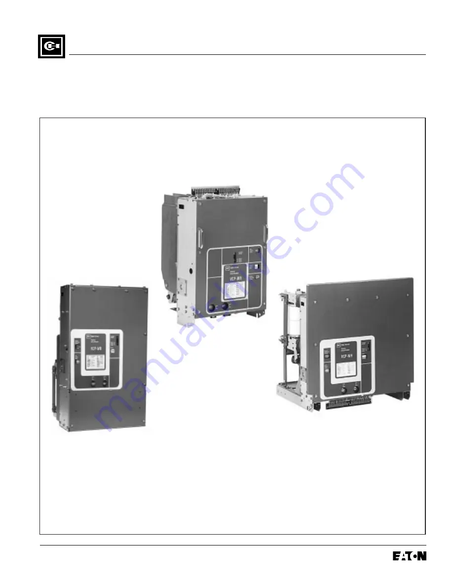
Instructions for the Use, Operation and Maintenance of TheRed Line Type VCP-WR Vacuum Circuit Breaker Elements
VCP-WR Series 29
VCP-WR Series 20
VCP-WR Series 18
Page 1: ...8295A61H03 Effective 7 97 Cutler Hammer Instructions for the Use Operation and Maintenance of The Red Line Type VCP WR Vacuum Circuit Breaker Elements VCP WR Series 29 VCP WR Series 20 VCP WR Series...
Page 2: ......
Page 3: ...ATTEMPTED ONLY BY QUALIFIED PERSONNEL THIS INSTRUCTION BOOK SHOULD NOT BE CON SIDERED ALL INCLUSIVE REGARDING INSTALLA TION OR MAINTENANCE PROCEDURES IF FUR THER INFORMATION IS REQUIRED YOU SHOULD CO...
Page 4: ...pection 19 4 2 Manual Operation Check 19 4 3 Interface Verification 19 SECTION 5 DESCRIPTION AND OPERATION 20 5 1 Circuit Breaker Elements 20 5 2 Interrupter Assembly 20 5 2 1 Vacuum Interrupter 20 5...
Page 5: ...erfacing Steps 31 6 4 2 Electrical Interfaces 32 6 4 3 Mechanical Interfaces 32 6 5 Series 29 Breaker Element Interfaces 33 6 5 1 Initial Interfacing Steps 33 6 5 2 Electrical Interfaces 33 6 5 3 Mech...
Page 6: ...nsfer System 23 5 6 Closing Cam and Trip Linkage 25 5 7 Charging Schematic 26 6 1 Typical VCP WR Front Cover Nameplate and Operational Indicators 29 6 2 Typical VCP WR DC and AC Control Schematics 30...
Page 7: ...LATE RATINGS WARNING Identification Rated Values Related Required Capabilities Current Nominal Nominal Voltage Insulation Level Rated Rated Rated Current Values Rated Rated Voltage 3 Phase Rated Rated...
Page 8: ...5 77 77 2 47 Ref See Expanded View Next Page 30 16 Ref 600A 1200A and 2000A Breaker Outline 10 70 13 33 50 350 12 06 63 1200A 2000A 25 600A 19 33 50 350 7 83 2 96 2 33 38 Dia 1 60 7 84 2 00 1 44 1 10...
Page 9: ...5 90 5 50 5 64 Trip Floor Tripper Close Floor Tripper 65 3 50 Ref 87 312 18 Clinch Nuts 9 Stroke Close and Trip Floor Trippers 750 500 Roller Dia 1 00 MOC Operator 750 Roller Dia 63 Stroke 1 25 3 13...
Page 10: ...ary Wiring TB See View Y Y 9 39 Trip Close Floor Tripper 18 A A MOC 9 62 7 66 20 27 See View X X 22 85 12 15 4 03 Figure 1 2 VCP WR Series 20 Element Outlines and Dimensions inches Front View Side Vie...
Page 11: ...4 2 63 7 125 78 1 19 1 19 Secondary Wiring Access to TB 1 16 1 16 16 00 Close Trip 8 00 1 09 1 09 6 745 75 1 875 3 018 1 50 88 6 875 4 96 MOC SW 1 31 28 Nom 38 010 Bus Connection Important This Gap Di...
Page 12: ...t Travel 62 3 12 1 25 50 Dia 7 78 Ref Front 1 31 1 56 314 Dia 317 56 Travel 1 16 Bracket w Term Blocks Breaker Bottom Pan Front View 3 89 12 12 1 25 2 1 3 4 5 6 7 8 9 10 11 13 12 14 15 16 17 18 19 20...
Page 13: ...eDetailY 10 10 C L B A Remove andReplace SeeDet D 12 13 88 1 00 2 25 20 875 24 63 Ref 7 78 Ref C L C L C L 12 x 4 or 5 CU Bar as Req Flex Conn 12 x 4 or 5 CU Bar as Req Flex Conn 1 0 1 0 1 0 1 0 1 0 1...
Page 14: ...nsu Current Detail lator Type 60Hz A B C Figure 50 VCP WR 250 1200A A 3 5 17 38 29 19 1 2000A C 3 5 17 38 29 19 1 3000A D 3 5 16 38 30 97 2 50 VCP WR 350 1200A B 3 5 17 38 30 97 1 2000A C 3 5 17 38 30...
Page 15: ...ion always make sure that primary and sec ondary power are disconnected from the breaker Failure to do so could result in electrical shock leading to death severe personal injury or property damage Do...
Page 16: ...ifting device or by a fork lift truck If containers must be skidded for any distance it is preferable to use roller conveyors or individual pipe rollers Once a breaker has been inspected for shipping...
Page 17: ...nt condensation If the building is not heated the same general rule for heat as for outdoor storage should be applied 3 4 TYPE VCP WR BREAKER WEIGHTS Table 3 1 VCP WR Breaker Weights pounds Series Rat...
Page 18: ...age 12 Effective 7 97 Figure 3 1 Front View VCP WR Series 18 5 3 6 1 2 4 Secondary Terminal Block Front Panel Close Floor Tripper Trip Floor Tripper Lifting Yoke Opening Escutcheon Figure 3 7 for Deta...
Page 19: ...ective 7 97 Figure 3 2 Rear View VCP WR Series 18 5 3 7 6 1 2 4 Support Insulator Primary Conductor Interface Vacuum Interrupter Contact Loading Spring Wipe Spring Operating Rod Drive Insulator Flexib...
Page 20: ...4 Effective 7 97 Figure 3 3 Front View VCP WR Series 20 5 3 1 2 4 Secondary Terminal Block Behind Front Panel Front Panel Floor Trippers Behind Front Panel Lifting Yoke Opening Escutcheon Figure 3 7 f...
Page 21: ...5A61H03 Page 15 Effective 7 97 Figure 3 4 Rear View VCP WR Series 20 5 3 1 2 4 Support Insulator Primary Conductor Interface Vacuum Interrupter Contact Loading Spring Wipe Spring Flexible Connector 1...
Page 22: ...A61H03 Page 16 Effective 7 97 Figure 3 5 Front View VCP WR Series 29 5 3 1 2 4 Secondary Terminal Block Front Panel Floor Trippers Not Visible Lifting Yoke Opening Escutcheon Figure 3 7 for Details 5...
Page 23: ...A61H03 Page 17 Effective 7 97 Figure 3 6 Rear View VCP WR Series 29 5 3 1 2 4 Standoff Insulator Primary Conductor Interface Vacuum Interrupter Contact Loading Spring Wipe Spring Flexible Connector 5...
Page 24: ...7 97 Figure 3 7 Typical VCP WR Escutcheon 5 3 8 7 6 1 2 4 Front Panel Manual Charge Socket Open Closed Indicator Spring Charged Discharged Indicator 6 1 2 4 5 3 8 7 Operation Counter Nameplate Manual...
Page 25: ...ng and charge the closing springs with approximately 38 up and down strokes of the han dle Figure 3 7 When charging is complete the closing crank goes over center with an audible click and the springs...
Page 26: ...gure 5 1 Circuit breaker duty vacuum interrupters are used to close and open primary circuits The vacuum interrupters used have a proven record for reliability long life and minimal maintenance Figure...
Page 27: ...4 11 12 9 13 10 L H Closing Spring Anti Pump Relay Auxiliary Switch Motor Cutoff Switch Closing Cam Spring Release Close Coil Assembly Shunt Trip Assembly Charging Motor Charging Pawl Ratchet Wheel R...
Page 28: ...n mark placed on each moving stem from the rear of the breaker with the breaker closed The interrupter is satisfactory if the mark on the stem is visible with the breaker closed The entire interrupter...
Page 29: ...the need for field adjustments of wipe or stroke THERE IS NO PROVISION FOR IN SERVICE ADJUSTMENTS OF CONTACT WIPE AND STROKE ALL SUCH ADJUSTMENTS ARE FACTORY SET AND SHOULD NOT BE ATTEMPTED IN THE FIE...
Page 30: ...ed to the cam shaft in turn rotates the pole shaft through the main link to close the breaker In Figure 5 6c the linkage is shown with the breaker in the closed position before the closing springs hav...
Page 31: ...igure 5 6b Breaker open and closing spring charged Figure 5 6a Breaker open and closing spring discharged Figure 5 6c Breaker closed and closing spring discharged 9 11 5 6 4 8 7 3 10 2 1 12 Pole Shaft...
Page 32: ...Pole Shaft Anti Close Interlock Spring Release Close Latch Spring Crank Closing Spring Closing Spring Fixed End Spring Release Close Coil Figure 5 7 Charging Schematic 9 11 5 6 4 8 7 3 10 2 1 12 Cam...
Page 33: ...Table 5 1 5 4 2 TERMINAL BLOCKS All VCP WR breaker elements are supplied with 2 12 point secondary control terminal blocks for simple sec ondary control access A number of points are used for breaker...
Page 34: ...is clearly indicated on the breaker s nameplate located on the front cover 6 2 2 INTERPHASE BARRIERS ANSI standards requires specific minimum air space clearances between poles for specific BIL applic...
Page 35: ...mechanical interfaces to insure that the Series 18 ele ment is properly installed and applied in a fixed or dra wout configuration Depending upon the final applied configuration the customer is respon...
Page 36: ...V 10UV 9A 10A 13 23 18 52 51 7 12 14 a a 11 MUST ADD JUMPERS AT TERMINAL BLOCK WHEN ST2 OPTION IS USED OPTIONS AC SOURCE 52 51 7 18 54 53 17 58 57 15 8 10 23 13 22 3 a b NOT AVAILABLE WHEN SECOND TRIP...
Page 37: ...ntacts in the breaker The MOC switch operator is located on the bottom of the Series 18 breaker element Figure 6 4 An optional additional top MOC drive is available in the form of a kit Style 8794C82G...
Page 38: ...is responsible for providing all properly sized primary connections to the VCP WR breaker ele ment whether the connections take the form of cable or bus bar Figure 6 5 The Series 20 outline drawing F...
Page 39: ...h points are used for breaker operation and which are available for customer use Figure 6 2 6 5 3 MECHANICAL INTERFACES The customer is responsible for providing all required mechanical interfaces to...
Page 40: ...ries 29 outline drawing Figure 1 3 for specific details as to exact loca tions and the amount of travel associated with each trip per MOC Operator The MOC Mechanism Operated Control switch opera tor i...
Page 41: ...UM INTEGRITY FAILURE TO FOLLOW ANY OF THESE INSTRUC TIONS MAY CAUSE DEATH SERIOUS BODILY INJURY OR PROPERTY DAMAGE SEE SECTION 2 SAFE PRACTICES FOR MORE INFORMATION 7 2 FREQUENCY OF INSPECTION Inspect...
Page 42: ...lace pole unit assembly Dirt on ceramic body Visual Check Clean with dry lint free cloth 3 Control Closing and Tripping Device Smooth and correct Test closing and tripping of Replace any defective Cir...
Page 43: ...test due to leakage or dis placement capacitive current the test unit should have sufficient volt ampere capacity It is recommended that the equipment be capable of delivering 25 milliamperes for one...
Page 44: ...ons and damage to insulation 7 7 INSULATION INTEGRITY CHECK Primary Circuit The integrity of primary insulation may be checked by the AC high potential test The test voltage depends upon the maximum r...
Page 45: ...ker several times manu ally and electrically Check the closing and opening times to verify that they are in accordance with the limits in Table 5 1 7 10 LUBRICATION All parts that require lubrication...
Page 46: ...Wipe Satisfactory Red or Gray Indicator Not Visible Wipe Unsatisfactory Any part of T Shape Indicator Visible Wipe Satisfactory T Shape Indicator Not Visible Wipe Unsatisfactory Any part of Indicator...
Page 47: ...ntrol Power fuse blown or switch off Secondary Disconnects Motor Cut off Switch Poor or burned contacts Lever not operational Terminals and connectors Poor or burned contacts Motor Brushes worn or com...
Page 48: ...tch or trip bar not reset Auxiliary Switch b contact open or burned Motor Cut off Contacts open or burned Trip Coil Assembly Clapper fails to reset Pole Shaft Not open fully Trip Latch Reset Spring Da...
Page 49: ...rminals and Connections Poor or burned or open Trip Mechanism Trip Clapper Jammed Trip Bar Trip Latch Jammed Trip Sound Trip Mechanism Pole Shaft But No Trip Jammed Operating Rod Assembly Broken or pi...
Page 50: ...ce severity and con tinuity requirements Each customer should develop his own stock level based on operating experience Table 8 1 8 2 ORDERING INSTRUCTIONS a Always specify the breaker rating informot...
Page 51: ...9WR VCP 29WRSE Interrupter Assembly 50 250 1200A 58kA 4 3A73901H01 50 250 1200A 58kA 4 SC 3A73901H21 50 250 2000A 58kA 5 3A73902H01 50 250 2000A 58kA 5 SC 3A73902H21 50 250 3000A 58kA 3A73903H01 50 35...
Page 52: ...e Cont Current C L VCP 29WR VCP 29WRSE 75 500 1200A 66kA 3A73907H01 3A73907H02 75 500 2000A 66kA 3A73908H01 3A73908H02 75 500 3000A 66kA 3A73909H01 3A73909H02 150 500 1200A 37kA 4 3A73910H01 3A73910H0...
Page 53: ...mber Style Number Type Cont Current C L VCP 29WR VCP 29WRSE 150 750 1200A 58kA 3A73913H01 3A73913H02 150 750 2000A 58kA 3A73914H01 3A73914H02 150 750 3000A 58kA 3A73915H01 3A73915H02 150 1000 1200A 77...
Page 54: ...3919H01 50 250 2000A 58kA 3A73920H01 50 350 1200A 78kA 3A73921H01 50 350 2000A 78kA 3A73922H01 Table 8 1 Recommended VCP WR Spare Parts Continued Description Style Number Style Number Type Cont Curren...
Page 55: ...Description Style Number Type Cont Current C L VCP 18WR 50 250 1200A 58kA 3A73923H01 50 350 1200A 78kA 3A73932H01 50 250 2000A 58kA 3A73924H01 50 350 2000A 78kA 3A73933H01 75 500 1200A 66kA 3A73925H01...
Page 56: ...tion Style Number Type Cont Current C L VCP 18WR 150 500 2000A 37kA 3A73929H01 150 750 1200A 58kA 3A73930H01 150 750 2000A 58kA 3A73931H01 Description Style Number Style Number VCP 29WR VCP 29WRSE Pha...
Page 57: ...29WR VCP 29WRSE Push Rod Assemblies Up to 5kV 692C799G01 BLUE SPRINGS Up to 5kV 692C799G02 RED SPRINGS Up to 15kV 691C650G01 691C650G02 WHITE SPRINGS Up to 15kV 691C651G01 691C651G02 BLUE SPRINGS Up...
Page 58: ...B19H01 686C575H01 350 1000MVA 1200 2000A Shock Absorber Up to 15kV 5677B26H01 5677B26H01 350 1000MVA 1200 2000A 63kA Description Style Number VCP 20WR Phase Barriers Up to 5kV 690C846H01 Push Rod Asse...
Page 59: ...Style Number VCP 18WR Phase Barriers Up to 15kV 5677B34H01 except 50 350 1200A 2000A 5677B36H01 Shock Absorber 5677B26H01 Description Style Number VCP 29WR VCP 29WRSE VCP 20WR VCP 18WR Charging Motor...
Page 60: ...7H03 8237A27H03 8237A27H03 8237A27H03 125VDC 8237A27H04 8237A27H04 8237A27H04 8237A27H04 250VDC 8237A27H05 8237A27H05 8237A27H05 8237A27H05 120VAC 8237A27H01 8237A27H01 8237A27H01 8237A27H01 240VAC 82...
Page 61: ...h 699B199G04 699B199G04 699B199G04 Motor Cutoff Switch 5677B02G11 Latch Check Switch 699B147G01 699B147G01 699B147G01 699B147G01 Position Switch 1 699B147H01 699B147H01 699B147H01 699B147H01 Position...
Page 62: ...94C84G12 125VDC 120CAP 8794C84G12 125VDC 120CAP 8794C84G02 125VDC 120CAP 8794C84G13 250VDC 240CAP 8794C84G13 250VDC 240CAP 8794C84G03 250VDC 240CAP 8794C84G14 24VDC 8794C84G14 24VDC 8794C84G03 24VDC A...
Page 63: ...e contract between the purchaser and Cutler Hammer NO WARRANTIES EXPRESSED OR IMPLIED INCLUDING WARRANTIES OF FITNESS FOR A PAR TICULAR PURPOSE OR MERCHANTABILITY OR WARRANTIES ARISING FROM COURSE OF...