background image

4

Congratulations for selecting the new WESLO

®

PURSUIT G 2.8 exercise cycle. Cycling is one of the

most effective exercises for increasing cardiovascular

fitness, building endurance, and toning the body. The

PURSUIT G 2.8 exercise cycle offers a selection of

features designed to let you enjoy this healthful exer-

cise in the convenience and privacy of your home.

For your benefit, read this manual carefully before

you use the exercise cycle.

If you have questions

after reading this manual, please see the front cover

of this manual. To help us assist you, note the product

model number and serial number before contacting

us. The model number and the location of the serial

number decal are shown on the front cover of this

manual.

Before reading further, please review the drawing

below and familiarize yourself with the labeled parts.

Resistance Knob

Seat

Seat Knob

Pedal/Strap

Console

Thumb Pulse Sensor

Handlebar

Leveling Cap

BEFORE YOU BEGIN

Summary of Contents for Pursuit G 2.8

Page 1: ...e above for reference QUESTIONS If you have questions or if parts are damaged or missing DO NOT CONTACT THE STORE please contact Customer Care IMPORTANT Please register this product see the limited warranty on the back cover of this manual before contacting Customer Care CALL TOLL FREE 1 866 699 3756 Mon Fri 6 a m 6 p m MT Sat 8 a m 4 p m MT ON THE WEB www wesloservice com Serial Number Decal www ...

Page 2: ...ING 19 ORDERING REPLACEMENT PARTS Back Cover LIMITED WARRANTY Back Cover WARNING DECAL PLACEMENT This drawing shows the location s of the warning decal s If a decal is missing or illegible call the telephone number on the front cover of this manual and request a free replacement decal Apply the decal in the location shown Note The decal s may not be shown at actual size WESLO is a registered trade...

Page 3: ...rcise clothes while exercising do not wear loose clothes that could become caught on your exercise cycle Always wear athletic shoes for foot protection while exercising 9 When adjusting the seat insert the seat pin into one of the holes in the seat post Do not insert the seat pin under the seat post 10 The pulse sensor is not a medical device Various factors including the user s move ment may affe...

Page 4: ... benefit read this manual carefully before you use the exercise cycle If you have questions after reading this manual please see the front cover of this manual To help us assist you note the product model number and serial number before contacting us The model number and the location of the serial number decal are shown on the front cover of this manual Before reading further please review the dra...

Page 5: ...pack ing materials Do not dispose of the packing materials until assembly is completed In addition to the included tool s assembly requires a Phillips screwdriver an adjustable wrench and pliers As you assemble the exercise cycle use the drawings below to identify the small parts used in assembly The number in parentheses below each drawing is the key number of the part from the PART LIST near the...

Page 6: ... the Frame 1 Attach the Front Stabilizer to the Frame with two M8 x 73mm Button Screws 33 1 1 2 33 2 Large Holes 3 Attach the Seat 12 to the Seat Post 5 with four M8 Split Washers 42 and four M8 Locknuts 10 Note The Split Washers and the Locknuts may be preattached to the underside of the Seat 3 12 5 42 42 42 10 10 To make assembly easier read the information on page 5 before you begin ...

Page 7: ...ect the Resistance Cable 19 to the Lower Cable 29 in the following way See drawing A Pull up on the metal bracket on the Lower Cable 29 and insert the tip of the Resistance Cable 19 into the wire clip inside of the metal bracket as shown See drawing B Firmly pull the Resistance Cable 19 upward and slide it into the top of the metal bracket as shown See drawing C Using pliers squeeze the prongs on ...

Page 8: ...x 16mm Screws 46 8 23 46 13 Console Wire 16 7 The Console 16 requires four AA batteries not included alkaline batteries are recommended IMPORTANT If the Console has been exposed to cold temperatures allow it to warm to room temperature before inserting batteries Otherwise you may damage the console display or other electronic compo nents Remove the battery cover and insert batteries into the batte...

Page 9: ...the Left Pedal counter clockwise into the left arm of the Crank 21 Tighten the Right Pedal not shown clockwise into the right arm of the Crank IMPORTANT Tighten both Pedals as firmly as possible After using the exercise cycle for one week retighten the Pedals For best performance keep the Pedals tightened Adjust the strap on the Left Pedal 24 to the desired position and press the end of the strap ...

Page 10: ...nd turn the seat knob clockwise until it is tight Make sure that the seat knob is inserted into one of the adjustment holes in the seat post HOW TO ADJUST THE PEDALING RESISTANCE To increase the resistance of the pedals turn the resistance knob clockwise to decrease the resis tance turn the resistance knob counterclockwise IMPORTANT Stop turning the knob when turning becomes difficult or you may d...

Page 11: ...he manual mode will be selected If you have select ed a pace work out reselect the manual mode by pressing the Pace Workouts button repeatedly until zeros appear in the display 3 Follow your progress with the display The display can show the following workout infor mation RPM The RPM meter on the left side of the dis play indicates your approximate pedaling pace revolutions per minute Speed This m...

Page 12: ...e On Reset button To pause the console stop pedaling If the time is displayed it will flash To continue your workout simply resume pedaling 4 Measure your heart rate if desired To measure your heart rate stop pedaling and place your thumb on the pulse sen sor Do not press too hard or the circula tion in your thumb will be restricted and your pulse will not be detected After a few seconds the heart...

Page 13: ...et pace is about to change the display will flash for a few seconds to alert you During the work out the pace guide will prompt you to keep your pedaling pace near the target pace for the current segment When the left indica tor lights increase your pace when the right indi cator lights decrease your pace When the center indicator lights maintain your current pace IMPORTANT The pace guide is inten...

Page 14: ...removed locate the Reed Switch 39 Turn the Crank 21 until the Magnet 38 is aligned with the Reed Switch Loosen but do not remove the M5 x 15mm Screw 47 Next slide the Reed Switch slightly closer to or away from the Magnet and retighten the Screw Then turn the Crank for a moment Repeat until the console displays cor rect feedback When the Reed Switch is correctly adjusted reattach the left shield t...

Page 15: ...our goal is to strengthen your cardiovascular system you must perform aerobic exercise which is activity that requires large amounts of oxygen for prolonged periods of time For aerobic exercise adjust the intensity of your exercise until your heart rate is near the highest number in your training zone WORKOUT GUIDELINES Warming Up Start with 5 to 10 minutes of stretching and light exercise A warm ...

Page 16: ...illes Stretch With one leg in front of the other reach forward and place your hands against a wall Keep your back leg straight and your back foot flat on the floor Bend your front leg lean forward and move your hips toward the wall Hold for 15 counts then relax Repeat 3 times for each leg To cause further stretching of the achilles tendons bend your back leg as well Stretches Calves achilles tendo...

Page 17: ...17 NOTES ...

Page 18: ...30 4 M8 x 60mm Button Screw 31 2 Eyebolt 32 2 M6 Locknut 33 2 M8 x 73mm Button Screw 34 3 M8 x 15mm Button Screw 35 1 Belt 36 1 Crank Bearing Set 37 1 Flywheel 38 2 Magnet 39 1 Reed Switch Wire 40 1 M8 x 20mm Bolt 41 10 M4 x 25mm Round Head Screw 42 9 M8 Split Washer 43 2 Flywheel Nut 44 1 M5 x 50mm Button Screw 45 1 M8 Washer 46 4 M4 x 16mm Screw 47 1 M5 x 15mm Screw 48 2 M4 x 15mm Screw 49 1 Han...

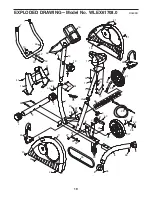
Page 19: ...5 2 4 30 29 9 31 32 37 38 28 31 32 28 11 1 33 41 22 39 20 5 10 10 12 42 42 21 24 26 36 34 42 42 10 46 8 27 6 43 23 47 41 41 41 41 4 8 15 14 41 41 44 43 27 45 25 3 40 48 48 49 10 42 42 50 38 EXPLODED DRAWING Model No WLEX61708 0 R0609B ...

Page 20: ...damage to a product caused by or attributable to freight damage abuse misuse improper or abnormal usage or repairs not provided by an ICON authorized service center to products used for commercial or rental purposes or as store display models or to products transported or purchased outside the US No other warranty beyond that specifically set forth above is authorized by ICON ICON is not responsib...

Reviews: