background image

8

10. Make sure that all parts of the elliptical glider are properly tightened. Place a mat under the elliptical glider

to protect the floor or carpet from damage.

9

57

5

47

Console
Wire

28

29

2

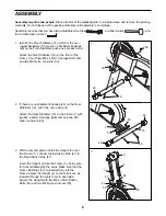
9. The Console (5) requires two “AA” batteries (not

included). Alkaline batteries are recommended. 

To install batteries, look under the Console (5) and
locate the battery compartment. Insert two batteries
into the battery compartment; make sure that the
batteries are turned so the negative ends (marked
“–”) are touching the springs in the battery com-
partment.

Connect the console wire to the Extension Wire (47).
Attach the Console (5) to the Upright (2) with four M4
x 12mm Button Screws (57).

Push the Resistance Knob (28) firmly onto the
Resistance Cable (29).

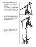
8. Identify the Left Pedal Arm (14), which is marked with

a sticker that has an “L” on it. Make sure that there are
two Pedal Arm Bushings (33) in the Left Pedal Arm.
Apply a thin film of the included grease to a Pedal
Axle (34). Insert the Pedal Axle into the Left Pedal
Arm, and slide a Pedal Washer (32) onto the Pedal
Axle. Firmly tighten the Pedal Axle into the Crank (30).
Tighten a 1/2” Nylon Locknut (35) onto the end of the
Pedal Axle protruding from the Crank.

Make sure that there are two Small Pivot Bushings
(42) in the Left Pivot Arm (6). Apply a thin film of the
included grease to an M8 x 60mm Bolt (56). Attach
the Left Pivot Arm to the Left Pedal Arm (14) with the
Bolt and an M8 Nylon Locknut (50).

Attach the Right Pedal Arm (not shown) in the same
manner.

8

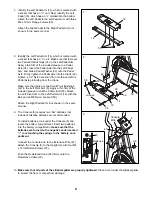
7. Identify the Left Pedal Arm (14), which is marked with

a sticker that has an “L” on it. Next, identify the Left
Pedal (16), which has an “L” molded into the bottom.
Attach the Left Pedal to the Left Pedal Arm with three
M4 x 19mm Flange Screws (55).

Attach the Right Pedal to the Right Pedal Arm (not
shown) in the same manner.

7

34

33

33

35

42

42

50

56

14

14

55

16

32

30

6

Batteries

5

Grease

Summary of Contents for Elliptical Glider 2.0

Page 1: ...atisfaction If you have questions or if there are missing parts we will guar antee complete satisfaction through direct assistance from our factory TO AVOID DELAYS PLEASE CALL DIRECT TO OUR TOLL FREE CUSTOMER HOT LINE The trained technicians on our customer hot line will provide immediate assistance free of charge CUSTOMER HOT LINE 1 800 999 3756 Mon Fri 6 a m 6 p m MST Patent Pending Visit our we...

Page 2: ...S 3 BEFORE YOU BEGIN 4 PART IDENTIFICATION CHART 5 ASSEMBLY 6 HOW TO USE THE ELLIPTICAL GLIDER 9 MAINTENANCE 11 CONDITIONING GUIDELINES 12 PART LIST 14 EXPLODED DRAWING 15 HOW TO ORDER REPLACEMENT PARTS Back Cover LIMITED WARRANTY Back Cover ...

Page 3: ...cal glider always hold the handlebars and step onto and off the pedal that is in the lowest position 10 Each time you stop exercising on the elliptical glider allow the pedals to come to a complete stop before dismounting 11 Always keep your back straight when using the elliptical glider Do not arch your back 12 If you feel pain or dizziness at any time while exercising stop immediately and begin ...

Page 4: ...lliptical glider If you have questions after reading the manual call our Customer Service Department toll free at 1 800 999 3756 Monday through Friday 6 a m until 6 p m Mountain Time excluding holidays To help us assist you please note the product model number and serial number before calling The model number is WLEL09910 The serial number can be found on a decal attached to the elliptical glider ...

Page 5: ... assembly Note Some parts may have been pre attached for shipping If a part is not in the parts bag check to see if it has been pre attached M8 x 19mm Button Screw 10 2 M8 x 63mm Carriage Bolt 49 4 M5 x 30mm Button Bolt 51 4 M8 x 38mm Button Bolt 53 2 M4 x 12mm Button Screw 57 4 M5 Nylon Locknut 52 4 M8 Nylon Locknut 50 8 1 2 Nylon Locknut 35 2 M8 x 60mm Bolt 56 2 Pivot Washer 54 2 Pedal Washer 32...

Page 6: ...olts 49 and two M8 Nylon Locknuts 50 2 If there are no Stabilizer Endcaps 20 on the Rear Stabilizer 19 push one onto each end Attach the Rear Stabilizer 19 to the Frame 1 with two M8 x 63mm Carriage Bolts 49 and two M8 Nylon Locknuts 50 3 While a second person holds the Upright 2 near the Frame 1 connect the Extension Wire 47 to the Reed Switch Wire 41 Insert the Upright 2 into the Frame 1 being c...

Page 7: ...m Grip down over the Button Bolts and Nylon Locknuts Attach the other Handlebar to the Left Pivot Arm 6 in the same manner 5 9 10 54 9 6 13 51 52 6 7 6 11 12 4 Make sure that the two Upright Bushings 8 are inserted into the Upright 2 Apply a thin film of the included grease to the length of the Pivot Axle 11 Insert the Pivot Axle into the Upright Bushings and the Upright Identify the Right Pivot A...

Page 8: ...hat there are two Pedal Arm Bushings 33 in the Left Pedal Arm Apply a thin film of the included grease to a Pedal Axle 34 Insert the Pedal Axle into the Left Pedal Arm and slide a Pedal Washer 32 onto the Pedal Axle Firmly tighten the Pedal Axle into the Crank 30 Tighten a 1 2 Nylon Locknut 35 onto the end of the Pedal Axle protruding from the Crank Make sure that there are two Small Pivot Bushing...

Page 9: ...variety to your exercise you may choose to turn the pedals in the opposite direction To dismount the elliptical glider allow the pedals to come to a complete stop CAUTION The elliptical glider does not have a free wheel the pedals will continue to move until the flywheel stops When the pedals are stationary step off the highest pedal first Then step off the lowest pedal HOW TO ADJUST THE RESISTANC...

Page 10: ...or simply begin pedaling When the power is turned on the entire display will appear for two seconds The console will then be ready for operation 2 Select one of the five modes Scan mode When the power is turned on the scan mode will automatically be selected One mode indicator will show that the scan mode is selected and a flashing mode indicator will show which mode is currently displayed Note If...

Page 11: ...quids away from the console Use only a sealable water bottle in the console CONSOLE TROUBLE SHOOTING If the console does not function properly the batteries should be replaced To replace the batteries refer to assembly step 9 on page 8 Note It will be necessary to remove the console to replace the batteries STORAGE When storing the elliptical glider remove the batteries from the console Keep the e...

Page 12: ...mounts of oxygen for prolonged periods of time This increases the demand on the heart to pump blood to the muscles and on the lungs to oxygenate the blood For aerobic exercise adjust the intensity of your exercise until your heart rate is near the largest number in your training zone HOW TO MEASURE YOUR HEART RATE To measure your heart rate first exer cise for at least four minutes Then stop exerc...

Page 13: ...illes Stretch With one leg in front of the other reach forward and place your hands against a wall Keep your back leg straight and your back foot flat on the floor Bend your front leg lean forward and move your hips toward the wall Hold for 15 counts then relax Repeat 3 times for each leg To cause further stretching of the achilles tendons bend your back leg as well Stretches Calves achilles tendo...

Page 14: ...1 Flywheel 22 1 Resistance Belt 23 1 Resistance Spring 24 1 Hook 25 1 Cable Clamp 26 1 Left Side Shield 27 1 Right Side Shield 28 1 Resistance Knob 29 1 Resistance Cable 30 1 Crank Pulley 31 1 Magnet 32 2 Pedal Washer 33 4 Pedal Arm Bushing 34 2 Pedal Axle 35 2 1 2 Nylon Locknut 36 1 Flywheel Axle 37 1 Bearing Set 38 1 Crank Nut 39 1 Belt Clamp 40 1 Reed Switch Clamp 41 1 Reed Switch Wire 42 4 Sma...

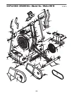
Page 15: ...0 20 20 21 22 23 24 25 26 28 29 30 31 33 33 33 34 34 35 35 36 37 38 39 40 41 42 42 42 42 43 43 44 44 46 46 50 49 49 50 50 50 50 20 51 51 52 52 53 53 50 50 55 55 56 50 56 50 59 59 59 59 60 60 57 48 48 58 59 58 58 54 54 47 32 45 32 EXPLODED DRAWING Model No WLEL09910 R0601A 15 ...

Page 16: ...ICON This warranty does not extend to any product or damage to a product caused by or attributable to freight damage abuse misuse improper or abnormal usage or repairs not provided by an ICON authorized service center to products used for commercial or rental pur poses or to products used as store displays No other warranty beyond that specifically set forth above is authorized by ICON ICON is not...

Reviews: