15
EN
OPERATING
INSTRUCTIONS
NOTE:
Before using the tool, read the instruction book
carefully.
INTENDED USE:
This tool is intended for the fastening and loosening of bolts, nuts
and various threaded fasteners. This tool is not intended for use
as a drill.
BEFORE OPERATION
1. CHARGING THE BATTERY PACK
a) Do not use any charger other than that specifically provided for
use with the equipment.
b) If the battery pack is very hot you must remove your battery pack
from the charger and allow time for the battery to cool down before
recharging.
c) The battery in your new tool is not charged when it leaves the
plant. Therefore it must be full charged before using the first time.
d) Please charge the battery to reach full or no less than half charge
before storage. If the tool will not be used for long periods of time,
charge the battery every 3-6 months.
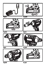
CHARGING PROCEDURE (SEE FIG. A1)
1) Plug the charger into an appropriate outlet. The light will be green.
2) Slide the battery pack into the charger, the light will turn to red to
indicate the charging process has started.
3) When charging is completed, the light will turn to green. The pack
is now fully charged, unplug the charger and remove the battery
pack.
CHARGING INDICATOR
This charger is designed to detect some problems that can arise
with battery packs. Indicator lights indicate problems (see table
below). If this occurs, insert a new battery pack to determine if the
charger is OK. If the new battery charges correctly, then the original
pack is defective and should be returned to a service center or
recycling service center. If the new battery pack displays the same
problem as the original Battery Pack, have the charger tested at an
authorized service center.
Light
Status
Red on
Charging
Green on
Fully Charged
WARNING: When battery charge runs out
after continuously use or exposure to direct
sunlight or heat, allow time for the tool to cool down
before re-charging to achieve the full charge.
2. REMOVE OR INSERT BATTERY PACK (SEE FIG.
A2, A3)
Press the battery pack release button and remove the battery
pack from the tool. After recharge slide the battery pack into tool’s
battery port. A simple push and slight pressure will be sufficient.
OPERATION
1. TO INSTALL OR REMOVE SOCKET ON THE
TOOL HOLDER (NOT SUPPLIED) (SEE FIG. B)
To install the socket, insert the socket onto the tool holder. To
remove the socket, pull the socket out of the tool holder.
WARNING: Inspect tool holders and socket
carefully before using the tool. Missing or
damaged items should be replaced. Make sure the
switch is locked off or remove the battery pack
before changing accessories.
2. ON / OFF SWITCH (SEE FIG. C)
Depress the on/off switch to start and release it to stop your tool.
The on/off switch is fitted with a brake function which stops your
chuck immediately when you quickly release the switch.
It is also a variable speed switch that delivers higher speed and
torque with increased trigger pressure. Speed is controlled by the
amount of switch trigger depression.
WARNING: Do not operate for long periods at
low speed because excess heat will be
produced internally. When overload occurs, release
the on/off switch immediately to avoid the motor
overheating.
3. SWITCH LOCK
The on/off switch can be locked in the OFF position. This helps to
reduce the possibility of accidental starting when not in use. To
lock the on/off switch, place the direction of rotation selector in the
center position.
4. REVERSIBLE (SEE FIG. D1, D2)
For forward rotation, (with chuck pointed away from you) move the
rotation control to the left.
For reverse rotation, (with chuck pointed away from you) move the
rotation control to the right.
WARNING: Never change the direction of
rotation when the chuck is rotating, wait until
it has stopped!
5. USING THE LED LIGHT
To turn on the light simply press the on/off switch. When you release
the on/off switch, the light will be off.
LED lighting increases visibility in dark or enclosed areas.
6. USING BELT CLIP (SEE FIG. E1,E2)
Screw the belt clip on the tool with the screw provided in the plastic
bag. The belt clip can be clipped on your belt or pocket, etc.
7. BATTERY CAPACITY INDICATOR
Your tool is equipped with battery capacity indicator. Press the on/
off switch halfway or fully, the battery capacity indicator will light up
to show the amount of charge left in the battery.
Fuel Gauge
Capacity
3 lights
>70%
2 lights
40%~70%
1 light
<40%
8. OVERLOAD PROTECTION
When overloaded, the motor comes to a stop. Relieve the load on
the machine immediately and allow cooling for approx. 30 seconds
at the highest no-load speed.
Summary of Contents for CIW18BWD
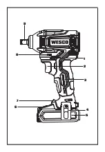
Page 2: ...1 2 3 4 5 6 7 9 8...
Page 3: ...1 2 Fig A1 Fig A2 Fig A3 Fig B Fig C Fig D1 Fig D2 Fig E1...
Page 4: ...Fig D2 Fig E1 Fig E2...
Page 23: ......
Page 24: ...Copyright 2021 Positec All Rights Reserved AR01562701...


