


REV. 01 2013
10 / 24
CHAPTER 4 – INSTALLATION
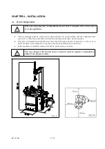
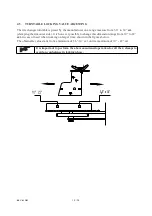
4.1 SPACE REQUIRED
When choosing the place of installation be sure that it complies with current safety
at work regulations
.
x
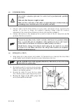
The tire changer must be connected to the main electric power supply and the compressed air
system. It is therefore advisable to install the machine near these power sources.
x
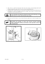
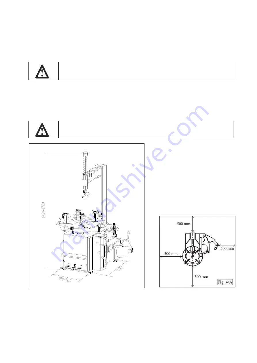
The place of installation must also provide at least the space shown in pictures 4 - 4/A so as to
allow all parts of the machine to operate correctly and without any restriction.
x
If the machine is installed outside it must be protected by a lean-to.
The tire changer with electric motor cannot be used in explosive atmospheres,
unless it is a proper version.
Fig . 4
Summary of Contents for TITANIUM BIKE
Page 2: ......
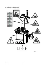
Page 9: ...REV 01 2013 7 24 2 3 DANGER WARNING SIGNS Fig 2 ...
Page 14: ...REV 01 2013 12 24 ...
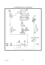
Page 26: ...REV 01 2013 24 24 STANDARD PNEUMATIC SYSTEM DIAGRAM ...
Page 27: ......
Page 28: ... 2 22 REV 01 2013 BODY TAV 1 1 ED 04 13 ...
Page 30: ... 4 22 REV 01 2013 HORIZ AND VERT ARMS TAV 2 1 ED 04 13 ...
Page 33: ... 7 22 REV 01 2013 PEDAL BOX TAV 3 1 ED 04 13 ...
Page 37: ... 11 22 REV 01 2013 BEAD BREAKER TAV 4 1 ED 04 13 ...
Page 40: ... 14 22 REV 01 2013 SELFͲCENTERING TURNTABLE TAV 5 1 ED 04 13 ...
Page 44: ... 18 22 REV 01 2013 3 MOTOR REDUCTION GEAR GROUP TAV 6 0 ED 04 13 ...
Page 47: ... 21 22 REV 01 2013 AIR LUBRICATOR GROUP TAV 8 1 ED 04 13 ...