background image

GB

SMONTAGOMME SEMIAUTOMATICO

SEMI AUTOMATIC TYRE CHANGER

DÉMONTE-PNEUS SEMI-AUTOMATIQUE

AUTOMATISCHE REIFENMONTIER

DESMONTADORA DE NEUMÁTICOS

SEMIAUTOMÁTICA

Werther interno e esplosi originali TAIDA

TITANIUM

BIKE

N/13

Summary of Contents for TITANIUM BIKE

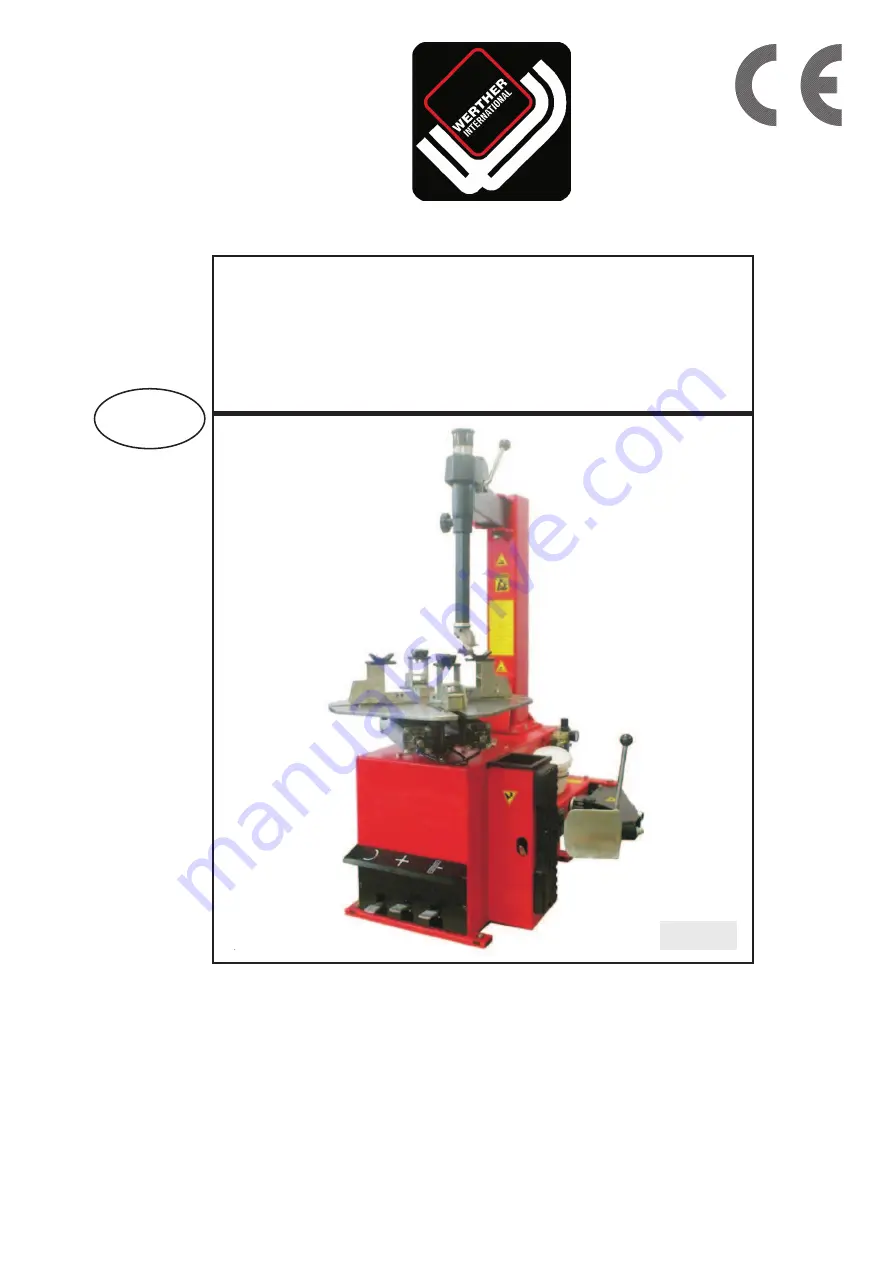
Page 1: ...GB SMONTAGOMME SEMIAUTOMATICO SEMI AUTOMATIC TYRE CHANGER DÉMONTE PNEUS SEMI AUTOMATIQUE AUTOMATISCHE REIFENMONTIER DESMONTADORA DE NEUMÁTICOS SEMIAUTOMÁTICA TITANIUM BIKE N 13 ...

Page 2: ......

Page 3: ... kart et roues ATV de 4 à 23 Halbautomatische Reifenmontiermaschine mit Schwenkarm für Motorräder Gokart und ATVReifen von 4 bis 23 Desmontadora de neumáticos semiautomática con brazo a bandera para ruedas de moto y motocicletas karts y ruedas ATV de 4 a 23 Modello Model Modèle Model Modelo TITANIUM BIKE COSTRUTTORE MANUFACTURER FABRICANT HERSTELLER FABRICANTE WERTHER INTERNATIONAL S p A Via F Bru...

Page 4: ...roughout this manual the following symbols and printing characters are used to facilitate reading Indicates the operations which need proper care Indicates prohibition ǂ Indicates a possibility of danger for the operators BOLD TYPE Important information ...

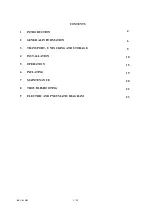
Page 5: ... 3 24 CONTENTS 1 INTRODUCTION 4 2 GENERAL INFORMATION 6 3 TRANSPORT UNPACKING AND STORAGE 9 4 INSTALLATION 10 5 OPERATION 15 6 INFLATING 19 7 MAINTENANCE 20 8 TROUBLESHOOTING 22 9 ELECTRIC AND PNEUMATIC DIAGRAM 23 ...

Page 6: ...s manual and that shown on the plate fixed to the tire changer the latter should be taken as correct 1 3 MANUAL KEEPING For a proper use of this manual the following is recommended x Keep the manual near the lift in an easily accessible place x Keep the manual in an area protected from the damp x Use this manual properly without damaging it x Any use of the machine made by operators who are not fa...

Page 7: ... changer comes complete with instruction and warning transfers which are designed to be long lasting If they should for any reason be damaged or destroyed please ask immediately for replacements from the manufacturer TO THE READER Every effort has been made to ensure that the information contained in this manual is correct complete and up to date The manufacturer is not liable for any mistakes mad...

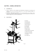
Page 8: ...URER cannot be held responsible for any damage caused through the use of this tire changer for purposes other than those specified in this manual and therefore inappropriate incorrect and unreasonable 2 2 DESCRIPTION G Clamps I Mounting head M Mounting bar N Horizontal arm P Vertical arm Q Air supply R Bead breaker S Wheel support U Bead breaker control pedal V Clamp control pedal Z Reverse contro...

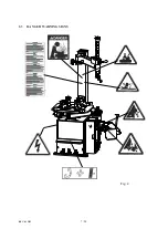
Page 9: ...REV 01 2013 7 24 2 3 DANGER WARNING SIGNS Fig 2 ...

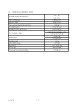
Page 10: ...n bead breaker blade 10 bar 3000 kg Working pressure 10 bar 145 psi Inflating pressure device max 3 5 bar 50 psi Power supply voltage 220V 380V 230V 400V 3 Ph 110V 220V 230V 1Ph Motor power 0 55kw 3Ph 0 75 kw 1ph Rotating speed 7 rpm Max spindle torque 1200 NM Dimension 975 x 760 x 950 Net weight 229 kg STND Noise level in working condition 70 dB A ...

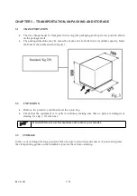
Page 11: ... Insert the forks at the points shown in figure 3 3 2 UNPACKING x Remove the protective cardboard and the nylon bag x Check that the equipment is in perfect condition making sure that no parts are damaged or missing Use fig 1 for reference If in doubt do not use the machine and contact your retailer 3 3 STORAGE In the event of storage for long periods of time be sure to disconnect all sources of p...

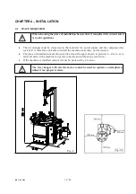
Page 12: ...ssed air system It is therefore advisable to install the machine near these power sources x The place of installation must also provide at least the space shown in pictures 4 4 A so as to allow all parts of the machine to operate correctly and without any restriction x If the machine is installed outside it must be protected by a lean to The tire changer with electric motor cannot be used in explo...

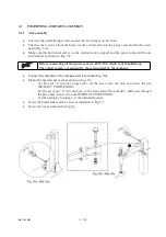
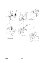
Page 13: ... power sources ALWAYS check your installations They must exactly correspond to those requested by the machine x Connect the machine to the compressed air network Fig 5 d x Mount the bead breaker arm as shown in Fig 5 e Set the arm a into the proper seat set the screw into the hole and screw the nut WITHOUT TIGHTENING Set the pivot pin b into the hole on the arm and let the cylinder s shaft pass th...

Page 14: ...REV 01 2013 12 24 ...

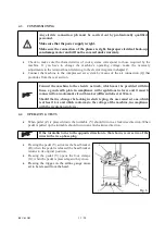
Page 15: ...line fuses a good earth plate in compliance with regulations in force and it must be connected to an automatic circuit breaker differential set at 30 mA Should the tire changer be lacking in electric plug the user must set one which is at least 16 A and which conforms to the voltage of the machine in compliance with the regulations in force 4 4 OPERATING TESTS x When pedal Z is pressed down the tu...

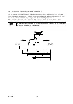
Page 16: ...e rim outer side It is however possible to change this dimension range from 10 to 22 ext in case of need when working on larger rims shown in the figures below The obtainable value starts from a minimum of 3 6 14 ext until a maximum of 10 22 ext It is important to perform the above mentioned operation for all the 4 clamps to avoid any unbalance in locking phase ...

Page 17: ...crushed x Check that the tire is deflated If not deflate it x Close the turntable clamps completely Bead breaking with the clamps in open position can be extremely dangerous for operator s hands During bead breaking operations NEVER touch the side of the tire x Position the wheel against the rubber stops on the right side of the tire changer S x Position the bead breaker R against the tire bead at...

Page 18: ...h vertical and horizontal direction and move the mounting head I of about 2 mm from the rim x With the lever T inserted between the bead and the front section of the mounting head I move the tire bead over the mounting head x With the lever held in this position rotate the turntable Y in a clockwise direction by pressing pedal Z down until the tire is completely separated from the wheel rim x Remo...

Page 19: ...u cannot identify the diameter of both x Lubricate the tire beads with the special grease in order to avoid damaging them and to facilitate the mounting operations During rim locking MEVER keep your hands under the tire For a correct locking operation set the tire exactly in the middle of turntable When working with rims of the same size it is not necessary always to lock and unlock the mounting b...

Page 20: ...le clockwise Continue until you have covered the entire circumference of the wheel rim Fig 12 To prevent industrial accidents keep hands and other parts of the body as far as possible from the tool arm when the table top is turning x Insert the inner tube if there is one and repeat the same operations to mount the upper side of the tire Demounting and mounting are always done with the clockwise tu...

Page 21: ...version our tire changer are supplied with an airline gauge To inflate a tire proceed as follows x Connect the airline gauge to the tire valve x Make a last check to be certain that tire and rim diameter correspond x Check to be certain that rim and beads are sufficiently lubricated If necessary lubricate some more x Seat the beads with short jets of air Between air jets check the air pressure on ...

Page 22: ...le for complaints deriving from the use of spare parts made by other manufacturers or for damage caused by tampering or removal of safety systems 7 2 MAINTENANCE OPERATIONS Clean the turntable once a week with diesel fuel so as to prevent the formation of dirt and grease the clamp sliding guides Carry out the following operations at least every 30 days x Check the oil level in the lubricator tank ...

Page 23: ... opening closing clamps see Fig 18 and proceed as follows 1 Remove the left side panel of the machine body by unscrewing the four fixing screws 2 Unscrewing the silencer put on the pedal system on the clamp opening closing pedal 3 Clean by a jet of compressed air or if damaged replace by referring to the spare parts catalogue For cleaning or replacing the silencer of bead breaker see Fig 19 and pr...

Page 24: ...lose Silencer clogged Clean or replace silencer Turntable does not lock the wheel rim correctly Clamps worn Replace clamps Turntable cylinder s defective Replace cylinder gasket The tool touches the rim during the tire removing or mounting operations Locking plate incorrectly adjusted or defective Adjust or replace locking plate chap 7 Fig 25 Turntable locking screw loose Tighten screw Pedal lock ...

Page 25: ...REV 01 2013 23 24 CHAPTER 9 ELECTRIC AND PNEUAMTIC DIAGRAM 110V 220V 230V 1PH 220V 230V 380V 400V 3PH SINGLE SPEED ...

Page 26: ...REV 01 2013 24 24 STANDARD PNEUMATIC SYSTEM DIAGRAM ...

Page 27: ......

Page 28: ... 2 22 REV 01 2013 BODY TAV 1 1 ED 04 13 ...

Page 29: ...YC1 3000069 Spring 1 9 YC1 3002102 Wheel support 1 10 0202033 Screw M6X20 GB T70 1 4 11 YC1 3002099 Plastic foot 4 12 YC1 3006970 Bead lifting lever 1 13 0203029 Nut M8 GB T6170 2 14 0205008 Washer D 8 GB T97 1 2 15 YC1 3011970 1 Front panel 1 16 0201026 Screw M8X16 GB T5783 2 17 YC3 2412452 C Pedal support 1 18 0201011 Screw M6X12 GB T5783 2 19 0205006 Washer D 6 GB T97 1 2 20 0202032 Screw M6X16...

Page 30: ... 4 22 REV 01 2013 HORIZ AND VERT ARMS TAV 2 1 ED 04 13 ...

Page 31: ...12 0201064 Screw M10X25 GB T5783 1 13 YC1 3015586 Hexagonal arm 1 14 YC1 4299952 Knob 1 15 YC1 2407085 Arm locking lever 1 16 0202030 Screw M6X10 GB T70 1 1 17 YC1 2002216 M C mounting tool unit 1 18 YC1 4295804 Conical washer 1 19 YC1 4295805 Spherical washer 1 20 0201059 Screw M10X16 GB T5783 1 21 YC1 3002602 Shock absorber protection 1 22 YC1 3002601 Shock absorber 1 23 0205011 Washer D 10 GB T...

Page 32: ...3012978 Inflator hook 1 31 0203004 Nut M6 GB52 1 32 YC1 3007801 A M C mounting tool 1 33 0209033 Screw M10X10 GB T80 2 34 YC1 3009018 Special screw 1 35 YC1 3000215 Peak roll 1 36 YC1 3006689 Plastic insert 1 37 0209044 Screw M10X12 GB T80 2 HORIZ AND VERT ARMS TAV 2 1 ED 04 13 ...

Page 33: ... 7 22 REV 01 2013 PEDAL BOX TAV 3 1 ED 04 13 ...

Page 34: ...11 0213003 Pin 4X25 GB T879 1 2 12 YC1 3007598 Valve pin 3 1 13 0207032 Self tapping screw 3 5X13 GB T845 6 14 YC1 3001585 Flange 2 15 YC1 3001584 Space 10 16 YC1 4299000 O ring 17X4 12 17 YC1 3001583 Valve body 2 18 0306059 Silencer 1 8 4 19 0306045 Quick union 8 1 8 4 20 0306023 Quick T union 8 1 8 1 21 YC1 4197629 Nylon washer 1 22 0205011 Washer D 10 GB T97 1 1 23 0205007 Washer D 6 GB T96 1 2...

Page 35: ...34 Self tapping screw 2 9X6 5 GB T845 2 39 YC1 3099910 Connecting rod guide 1 40 YC1 4299913 Double cam 1 41 YC2 4299910 Forked leaf spring 1 42 0204003 Self locking nut M6 GB T889 1 2 43 YC1 3015341 Connecting rod 1 44 0507115 Cable holder 1 45 0506016 Power cable L 3500 1 46 0506016 Motor cable L 1500 1 47 YC1 3015344 Reverser cover 1 48 0505009 Reverser 40A 1 49 0203002 Nut M4 GB52 2 50 0211016...

Page 36: ...YC1 3015340 Reverser support 1 56 0203004 Nut M6 Ͳ GB52 4 57 YC1 3015342 Support 1 58 YC1 2005000 Pedal control unit 1 59 YC1 2006297 Bead breaker valve unit 1 60 YC1 2002529 Turntable valve unit 1 PEDAL BOX TAV 3 1 ED 04 13 ...

Page 37: ... 11 22 REV 01 2013 BEAD BREAKER TAV 4 1 ED 04 13 ...

Page 38: ...893 1 1 12 0306097 Rilsan hose 8X5 L 700 1 13 0306032 90 quick union 8 1 4 1 14 YC1 3015834 B Piston rod 1 15 YC1 3015573 Bush 2 16 0202071 Screw M12X35 GB T70 1 2 17 0204025 Flange nut M8 GB T6177 1 12 18 C207010100 Front flange 1 19 0606011 O ring 195X3 55 2 20 C207010006 Cylinder liner 1 21 C207010007 Back flange 1 22 C207010005 Screw M8X255 GB T5782 12 23 C02AQ00100 Quick relief valve unit 1 2...

Page 39: ...ut M18 GB T889 1 1 32 0204005 Self locking nut M10 GB T889 1 1 33 0202057 Screw M10X70 GB T70 1 1 34 YC1 2415574 Bead breaker arm 1 35 YC1 3008990 Pivot pin 1 36 0204013 Nut M14 GB T6172 1 2 37 0208013 Elastic washer D 14 GB T955 1 38 0212008 Seeger D 40 GB T894 1 2 39 102 2413331 Bead breaker plate 1 40 YC1 4299952 Knob 1 BEAD BREAKER TAV 4 1 ED 04 13 ...

Page 40: ... 14 22 REV 01 2013 SELFͲCENTERING TURNTABLE TAV 5 1 ED 04 13 ...

Page 41: ...3452 1 1 11 0606016 Scraper 20X30X7 1 12 YC1 4398146 Washer 1 13 0211004 Seeger D 30 GB T893 1 1 14 0204025 Flange nut M8 GB T6177 1 4 15 YC1 3015024A Back flange 1 16 0606007 O ring 75X3 55 2 17 YC1 3008042 Cylinder liner 1 18 YC1 3007941 Special screw 4 19 YC1 3015023A Front flange 1 20 0306022 Quick T union D 8 1 21 0306097 Rilsan hose 8X5 L 850 2 22 0306106 90 rotation union 8 1 8 2 23 0306106...

Page 42: ...amp 4 40 YCF1 3005070 Clamp support 4 41 102 2480100 Slide 4 42 0204004 Self locking nut M8 GB T889 1 8 43 102 3080001 Steel shim 4 44 102 2415756 Slide guide 2 45 YC1 2003000 Rotation union 1 46 YC1 4298956 1 Inner element of rotation union 1 47 0209043 Screw M4X6 GB T77 4 48 0306001 Quick T union 8 1 8 1 49 0606006 O ring 60X2 65 3 50 YC1 2003001 Outer element of rotation union 1 51 0202030 Scre...

Page 43: ...V 01 2013 55 YC1 3007420 Bush 1 56 0201011 Screw M6X12 GB T5783 4 57 YC1 3006870 Connection plate 8 58 YC1 3006878 Pin 4 59 0203004 Nut M6 GB52 4 60 YC1 3015187 Rivet 8 SELFͲCENTERING TURNTABLE TAV 5 1 ED 04 13 ...

Page 44: ... 18 22 REV 01 2013 3 MOTOR REDUCTION GEAR GROUP TAV 6 0 ED 04 13 ...

Page 45: ... 1 11 0606005 O ring 34 5X3 55 GB T3452 1 1 12 YC1 4296942 Seal 1 13 0213028 Tab 6X18 GB T1096 1 14 0209009 Screw M8X16 GB T80 1 15 YC1 3000166 Motor pulley 1 16 202W ZYDJPJ Tab 6X30 GB T1096 1 17 0213027 Tab 16X70 GB T1096 1 18 YC1 3010885 Helical gear stud 1 19 YC1 3010883 Worm 1 20 0214007 Bearing 30204 GB T297 2 21 YC1 3010886 Seal cap 1 22 0202030 Screw M6X10 GB T70 1 2 23 0212010 Seeger D 60...

Page 46: ...a 0509065 1PH motor 230V 0 75KW 1 31b 0509053 3PH motor 230V 400V 0 55KW 1 32 0203029 Nut M8 GB T6170 4 33 0205008 Washer D 8 GB T97 1 4 34 0201062 Screw M10X20 GB T5783 2 35 YC1 3000149A Motor support 1 36 0201038 Screw M8X25 GB T5783 4 37 YC1 2011967 Reduction gear unit 1 MOTOR REDUCTION GEAR GROUP TAV 6 0 ED 04 13 ...

Page 47: ... 21 22 REV 01 2013 AIR LUBRICATOR GROUP TAV 8 1 ED 04 13 ...

Page 48: ... 1 8 1 6 0306106 Pressure relief valve 1 8 5 5bar 1 7 0306144 Quick union 8 1 4 1 8 0306011 Inflator 1 9 0306157 Rilsan spiral hose 8X5 L 2000 1 10 0306032 90 quick union 8 1 4 1 11 0202012 Screw M4X50 GB T70 1 2 12 0307065 Lubricator NL 200 1 13 0306052 Pressure gauge 1 14 0307065 Filter regulator NFR 200 1 15 0306007 T union 8 1 4 1 16 YC2 2012326 1 Lubricator filter regulator 1 AIR LUBRICATOR G...

Page 49: ...dello declara que la desmontadora de neumáticos modelo déclare que le monte demonte pneus modèle Vi erklærer dækskiftermodellen hereby we declare that the tyre changer model Vi deklarerer däckomläggermodellen hiermit erklären wir daß die Reinfenmontirgerät Wij verklaren dat de bandenwisselmachine TITANIUM BIKE Matricola N N de série Fascicolo tecnico Dossier technique Serial N Maschinennummer Tech...

Reviews:

Related manuals for TITANIUM BIKE