background image

15

6.8.  Information

The following information regarding the Sensor is displayed in the “Info” menu:
• Sensor type
• Sensor version

6.9.  Reset

Sensor settings can be returned to their default values with the help of the “Reset” menu.

6.10. Password

The Sensor can be locked by entering a password in the “Password” menu, so that setting can not be read-
justed.

Function

Description

Enable

Switching the Password Function On or Off
“Enable” or “Disable” can be selected with the 

5

 and 

6

 keys. 

The password function is thus switched on or off. If the password func-
tion is activated, Sensor operation is disabled after supply power has 
been interrupted. Immediate disabling is also possible with the help of the 
“Disable” submenu.

Enter

Password Entry for Enabling the Sensor
The password for enabling the Sensor is selected with the + or – key.* 
Selection is acknowledged by pressing the enter key.
The password is set to “0” upon shipment from the factory.

Change

Changing the Password

The desired new password is selected with the + or – key.* Selection is 
acknowledged and the password is changed by pressing the enter key.

Disabling

Disabling the Sensor
The Sensor is disabled without interrupting supply power. The Sensor is 
disabled by pressing the enter key, and the password entry window is 
displayed immediately. The Sensor is switched to the display mode after 
approximately 30 seconds. A password must be entered in order to  
continue using the Sensor.

Notes regarding password functions:
If the password function has been activated. the password must be entered each time supply power to the 
Sensor is interrupted. After pressing a key, the menu is automatically switched to the password entry mode.
After the password has been correctly entered, the entire menu is enabled and the Sensor can be operated.

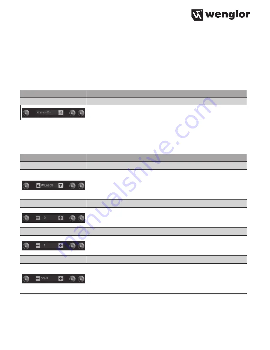
Function

Description

Reset

Default Settings
All of the selected Sensor settings are returned to their default values by 
pressing the R key.

Summary of Contents for OPT2041

Page 1: ...OPT2041 Fiber Optic Cable Sensor Operating Instructions Available as PDF only Status 18 06 2018 www wenglor com EN...

Page 2: ...tion Instructions 6 4 7 1 Mounting to a DIN rail 6 4 7 2 Side mounting 7 4 7 3 Connecting the plastic fibre optic cable 7 5 Initial Operation 8 5 1 Overview of Functions 8 5 2 Menu Structure 9 6 Adjus...

Page 3: ...t on the range 2 Safety Precautions This operating instruction is part of the product and must be kept during its entire service life Read this operating instruction carefully before using the product...

Page 4: ...oltage A Switching Output IO Link T Teach Input Supply Voltage 0 V 4 2 Housing Dimensions 1 Transmitter Diode 2 Receiver Diode 4 3 Declaration of Conformity The EC declaration of conformity can be fou...

Page 5: ...25 60 C Switching Output Voltage Drop 2 5 V Switching Output Switching Current 100 mA Short Circuit Protection yes Reverse Polarity Protection yes Overload Protection yes Teach Mode NT MT ZT DT FT HT...

Page 6: ...y 4 7 Installation Instructions All applicable electrical and mechanical regulations standards and safety precautions must be adhered to when installing and operating the Sensor The Sensor must be pro...

Page 7: ...nting of the Sensor 4 7 3 Connecting the plastic fibre optic cable Please cut the plastic fibre optic cable once before using with the cutting tool Open the mounting slide with a screwdriver see fig 3...

Page 8: ...functions of the navigation keys vary from menu to menu The functions of the keys appear in the display as follows 5 Navigate up 6 Navigate down 3 Back Move up one level within the menu 7 Run Switch...

Page 9: ...9 5 2 Menu Structure The Sensor s menu is laid out as follows normal Signal Strength Password Switching Status Indicator Only after Window Teach...

Page 10: ...e T key Align the spot to the object Briefly press the T key The switching distance to the object is set If necessary readjust the switching distance with the help of the Potentiometer menu item T Dyn...

Page 11: ...re displayed alternately while the window is being taught in T Background Background Teach In The background is taught in by pressing the T key so that it can be virtual suppressed Align the spot to t...

Page 12: ...selection is acknowledged by pressing the enter key NO NC Selecting the Output Function The normally open or normally closed output function is selected by press ing the NO or the NC key The respectiv...

Page 13: ...pressing the Enter key High Sensitivity Highest sensitivity for large ranges Normal Sensitivity Normal sensitivity for standard applications 6 5 Filter The filter function is set in the menu Filter Fu...

Page 14: ...ar graph is zoomed by pressing the 5 and 6 keys Display elements The elements which will appear at the display can be selected with the 5 and 6 keys and acknowledged by pressing the enter key Displaya...

Page 15: ...the enter key The password is set to 0 upon shipment from the factory Change Changing the Password The desired new password is selected with the or key Selection is acknowledged and the password is ch...

Page 16: ...and Process data Addressing via IO Link The Index is set to 1 at all times Thereby the Direct Parameter Page can be reached where then the several Parameters can be set by the Subindexes Subindex 0 re...

Page 17: ...f Configuration Page Bit 7 Switch to 1 Configuration Page Is Bit 7 in Parameter 0 set to 1 more Configuration Pages can be reached For this purpose the corresponding address of the Configuration Page...

Page 18: ...Page 0x80 Parameter 1 Serial number Byte 1 Parameter 2 Serial number Byte 2 Parameter 3 Serial number Byte 3 Parameter 4 Serial number Byte 4 Parameter 5 DeviceID Byte 1 Parameter 6 DeviceID Byte 2 P...

Page 19: ...Parameter 5 Low Byte of Lower Threshold 2 Parameter 6 High Byte of Upper Threshold 2 Parameter 7 Low Byte of Upper Threshold 2 Parameter 8 Parameter 9 Parameter 10 Parameter 11 8 Maintenance Instructi...

Reviews: