background image

7

ELECTRICAL INFORMATION

AMPERAGE

REQUIRED GAUGE FOR EXTENSION CORDS

25 ft.

50 ft.

100 ft.

150 ft.

15A

14 gauge

12 gauge

Not Recommended

Not Recommended

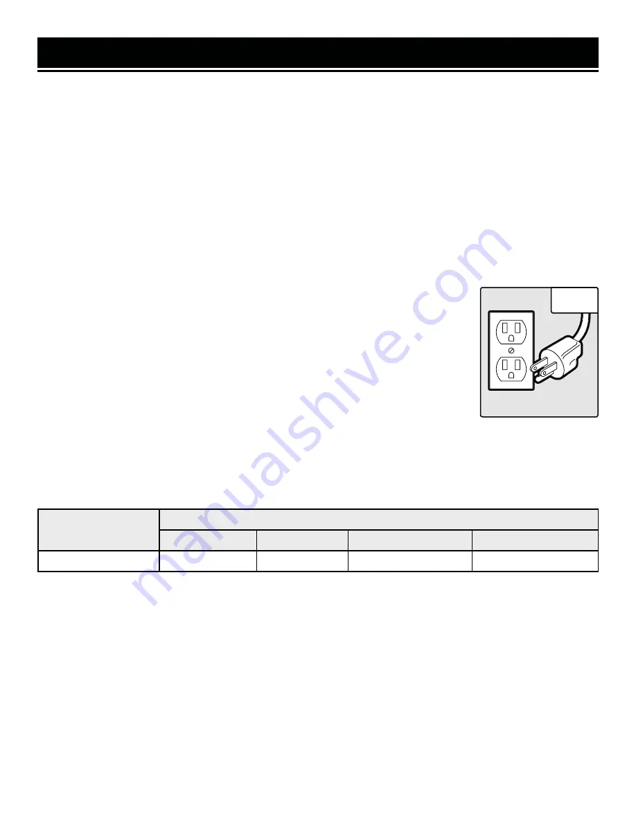
3. Check

 with a licensed electrician or service personnel if you do not completely 

understand the grounding instructions or whether the tool is properly grounded. 

4. Use only three-wire extension cords

 that have three-pronged plugs and outlets 

that accept the tool’s plug. Repair or replace a damaged or worn cord immediately. 

CAUTION!

 In all cases, make certain the outlet in question is properly grounded. If 

you are not sure, have a licensed electrician check the outlet.

GUIDELINES AND RECOMMENDATIONS FOR EXTENSION CORDS

When using an extension cord, be sure to use one heavy enough to carry the current your 

GROUNDING INSTRUCTIONS

In the event of a malfunction or breakdown

, grounding provides the path of least resistance for an electric 

current and reduces the risk of electric shock. This tool is equipped with an electric cord that has an 

equipment grounding conductor and a grounding plug. The plug MUST be plugged into a matching outlet 

that is properly installed and grounded in accordance with ALL local codes and ordinances.

1. Do not modify the plug provided.

 If it will not fit the outlet, have the proper outlet installed by a licensed 

electrician. 

2. Improper connection 

of the equipment grounding conductor can result in electric shock. The conductor 

with the green insulation (with or without yellow stripes) is the equipment grounding conductor. If repair or 

replacement of the electric cord or plug is necessary, DO NOT connect the equipment grounding conductor 

to a live terminal. 

1. Examine extension cord before use. 

Make sure your extension cord is properly wired and in good condition. 

Always replace a damaged extension cord or have it repaired by a qualified person before using it.

2. Do not abuse extension cord.

 Do not pull on cord to disconnect from receptacle; always disconnect by pulling on 

plug. Disconnect the extension cord from the receptacle before disconnecting the product from the extension cord. 

Protect your extension cords from sharp objects, excessive heat and damp/wet areas.

3. Use a separate electrical circuit for your tool.

 This circuit must not be less than a 12-gauge wire and should be 

protected with a 15A time-delayed fuse. Before connecting the motor to the power line, make sure the switch is in 

the OFF position and the electric current is rated the same as the current stamped on the motor nameplate. Running 

at a lower voltage will damage the motor.

product will draw. An undersized cord will cause a drop in line voltage resulting in loss of power and overheating. 

The table below shows the correct size to be used according to cord length and ampere rating. When in doubt, use 

a heavier cord. The smaller the gauge number, the heavier the cord. 

Fig. 1 

Summary of Contents for PL1303

Page 1: ...gged trouble free performance Pay close attention to the rules for safe operation warnings and cautions If you use your tool properly and for its intended purpose you will enjoy years of safe reliable...

Page 2: ...Adjustments 10 OPERATION MAINTENANCE 11 Operation 11 Maintenance 16 Troubleshooting Guide 18 Exploded View Parts List 20 Warranty Statement 23 2 To purchase accessories for your tool visit WENPRODUCT...

Page 3: ...for the most up to date manual or contact our customer service at 1 800 232 1195 Keep this manual available to all users during the entire life of the tool and review it frequently to maximize safety...

Page 4: ...ock PERSONAL SAFETY 1 Stay alert watch what you are doing and use com mon sense when operating a power tool Do not use a power tool while you are tired or under the influence of drugs alcohol or medic...

Page 5: ...ordance with these instructions taking into ac count the working conditions and the work to be per formed Use of the power tool for operations different from those intended could result in a hazardous...

Page 6: ...1 Never make a cut deeper than 1 8 12 For workpieces longer than 24 use material support stands 13 Always feed from infeed side to outfeed side and do not attempt to reverse direction of workpiece bei...

Page 7: ...connection of the equipment grounding conductor can result in electric shock The conductor with the green insulation with or without yellow stripes is the equipment grounding conductor If repair or re...

Page 8: ...rything is removed Check the packing list below to make sure you have all of the parts and accessories If any part is missing or broken please contact customer service at 1 800 232 1195 M F 8 5 CST or...

Page 9: ...our WEN Thickness Planer Refer to the diagram below to become familiarized with the parts and controls of your thickness planer KNOW YOUR PLANER PLANER Circuit Breaker Power Switch Extension Table Ele...

Page 10: ...owever if you find that they are out of adjustment from shipping follow the directions on p 17 to adjust them ATTACHING THE DUST CHUTE 1 Make sure the hex wrench and star wrench are mounted on the dus...

Page 11: ...ld safety lock and prevent unwanted start ups To lock the switch flip the switch to the OFF position and disconnect the planer from its power source Pull the safety key out Fig 6 2 The machine cannot...

Page 12: ...e The quality of the finished surface de pends on the operator s experience and judgment about the depth of cut Each full rotation of the depth adjustment handle adjusts the planer s height by 1 16 Fo...

Page 13: ...eforehand As a rule of thumb it is best to alternate sides of the board being planed until the desired thickness is reached This will result in the board having a more uniform moisture content since h...

Page 14: ...can be ordered from wenproducts com model numbers BP133K and BP133M AVOIDING SNIPE Thickness planers tend to leave a small bit of snipe at the end of the planed boards particularly for longer work pie...

Page 15: ...lar to the rollercase so that the work feeds through the planer straight making sure that the board is traveling in the same direction as the grain and that you are only planing either side or face gr...

Page 16: ...t remove the bolts from the gib 5 With the hook and loop side of the magnetic blade tool facing down slide the magnetic strip between the blade and the gib Make sure the tool is centered on the blade...

Page 17: ...ularly inspect brushes after 100 hours of use Brushes are located on either side of the planer motor on both the front and rear side of the planer Loosen brush cap Fig 12 1 and carefully remove brush...

Page 18: ...only be performed by an authorized technician For any questions please contact our customer service at 1 800 232 1195 M F 8 5 CST or email us at techsupport wenproducts com 18 CLEANING THE PLANER Kee...

Page 19: ...fed against grain Reverse workpiece Table or feed rollers are dirty Clean table and or feed rollers Dust or debris between cutting inserts and cutterhead Clean cutting inserts and cutterhead Snipe Du...

Page 20: ...EXPLODED VIEW PARTS LIST 20 NOTE Not all parts may be available for purchase Parts and accessories that wear down over the course of normal use are not covered under the warranty...

Page 21: ...1 R32 Handwheel Bracket 1 33 Chain Sprocket 4 34 Spring 1 35 Depth Stop Knob 1 36 Depth Stop Cover 1 37 Socket Head Cap Screw M6 1x12 1 No Part No Description Qty 38 Bearing Retainer Washer 4 39_S PL1...

Page 22: ...d 1 136 Adjusting Screw M10 1 5 4 137 Hex Nut M10 1 5 4 140 Hex Screw M6 1x25 4 141 Hex Nut M6 1 4 EXPLODED VIEW PARTS LIST No Part No Description Qty 142 Ball Bearing 5 143 Washer 4 144 Socket Head C...

Page 23: ...arts and products may need to be sent to WEN before the replacements can be shipped out turning a product for warranty service the shipping charges must be prepaid by the purchaser The product must be...

Page 24: ...THANKS FOR REMEMBERING V 2020 11 24...

Reviews: