background image

1

GENERAL INSTALLATION INFORMATION

The unit is shipped ready to be hardwired to an electrical box specified for its voltage and amp 

draw. If improper electrical supply can not be determined through troubleshooting, contact a 

qualified electrician prior to using the unit. Improper electrical installation can void the warranty. 

Should you require assistance, contact your local authorized service agent for any service or 

required maintenance.  

Allow enough space around the induction unit for adequate ventilation and make certain the 

cooling fan is not blocked. Additional space from extremely hot devices is recommended as this 

unit’s intake air temperature cannot exceed 104° F (40° C). Doing so may result in damage to the 

induction unit. Make certain this induction unit is not located near other appliances which may 

produce grease vapor, such as fryers, griddles, etc.

Before using the induction unit for the first time, ensure to clean it properly. Refer to the Cleaning 

section for cleaning instructions.

ELECTRICAL CONNECTION

Before making any electrical connections to this 

unit, check that the power supply is adequate for 

the voltage, amperage, phases, and requirements 

stated on the rating plate. This equipment must 

be installed and connected in accordance with all 

applicable federal, state, province, and/or local 

electrical codes having jurisdiction by a licensed 

electrician. All electrical connections must be 

made with COPPER WIRE ONLY in the correct 

wire gauge for the application. The induction units 

will utilize a terminal block ready to be connected 

through a plug and receptacle-type connection or 

direct flexible conduit. Do not use rigid conduit to 

connect to the supply. ALLOW ENOUGH SLACK in 

the wiring to allow for equipment to be moved during installation or any required maintenance and 

servicing. Be absolutely certain that the ground connection for the receptacles is properly wired. 

Do not connect equipment to power without proper ground connections. Improper grounding 

may result in a void to warranty, personal injury, or fatality.

DO NOT CUT OR REMOVE THE 

PLUG OR GROUNDING PRONG 

FROM THE PLUG ON THE 

INDUCTION UNITS. 

CONNECT/PLUG UNIT INTO 

DEDICATED AC LINE ONLY 

SPECIFIED ON THE DATA PLATE 

OF THE UNIT. 

MAKE CERTAIN THE UNIT IS 

POWERED OFF AND UNPLUGGED 

PRIOR TO ANY REPAIRS OR 

MOVEMENT. ALL REPAIRS SHOULD 

BE PERFORMED BY AUTHORIZED 

SERVICE TECHNICIANS ONLY.

DO NOT HOSE DOWN 

THE UNIT OR THE TABLE/

COUNTER IF THE UNIT IS ON 

THE  TABLE/COUNTER.

DO NOT IMMERSE OR LET 

THE UNIT STAND IN WATER.

KEEP AWAY FROM RUNNING 

WATER.

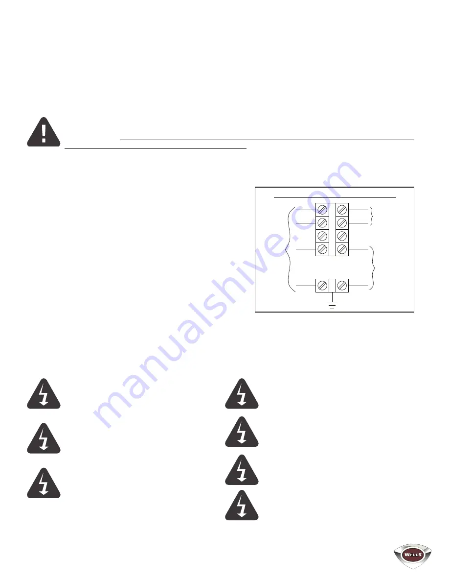
WARNING: Do Not connect 

to a circuit operating at more 

than 150 volts to ground.

BLACK

RED

WHITE

GREEN

OR BARE

COPPER

BLACK

RED

WHITE

GREEN

RECEPTACLES

MAIN CONTACTOR

L1

L2

N

MAIN SUPPLY

SUPPLY CONNECTION DIAGRAM

Summary of Contents for WDDI-31

Page 1: ...Street Smithville Tennessee 37166 Telephone 800 264 7827 Fax 314 781 5445 www wells mfg com WDDI 35 VENTLESS DOWNDRAFT INDUCTION RANGE TOP MODEL WDDI 31 WDDI 35 Installation and Operation Instructions...

Page 2: ...nge Top 2 TABLE OF CONTENTS GENERAL WARRANTY SAFETY INFORMATION INSTALLATION INFORMATION DAILY OPERATION CLEANING TROUBLESHOOTING FEATURES INSTALLATION CONTROL PANEL EXPLODED VIEW PARTS WIRING DIAGRAM...

Page 3: ...type Normal Business Hours 8 00 a m to 4 30 p m Central Telephone 800 264 7827 Tech Service Option 2 Email TechService partstown com www Wells Mfg com WARRANTY EXCLUSIONS THE FOLLOWING WILL NOT BE COV...

Page 4: ...ase have the information in the above fields ready when you call to ensure a faster service Using any part other than genuine Wells factory supplied parts relieves the manufacturer of all liability Du...

Page 5: ...uld keep a minimum of 2 4 inches 51 102 mm of space between them and the cooking zone whenever possible It is recommended that you keep this distance at minimum whenever the unit is powered on Failure...

Page 6: ...mber on page ii of this manual Read and understand all labels and diagrams attached to the downdraft Carefully account for all components and accessories before discarding packing materials COMPONENTS...

Page 7: ...e federal state province and or local electrical codes having jurisdiction by a licensed electrician All electrical connections must be made with COPPER WIRE ONLY in the correct wire gauge for the app...

Page 8: ...o wipe away and spilled food and debris If there is any hardened residue use a scraper or cleaning pad made specifically for glass ceramic surfaces and an appropriate glass ceramic cooktop cleaning so...

Page 9: ...ocedure 1 TURN POWER SWITCH TO OFF 2 Remove BAFFLE FILTERS and GREASE CUP 3 Empty GREASE CUP into an appropriate grease collection receptacle 4 Clean BAFFLE FILTERS and GREASE CUP in a sink or dishwas...

Page 10: ...ime to turn off the power stopping the cooker immediately COOKTEK CONTROLLER If the unit does not initially power on make certain the unit is plugged in properly and that the power supply is the corre...

Page 11: ...aning instructions and schedules to ensure the safety of the food product This appliance is not jet steam approved Do not direct water jet or steam jet at this appliance or at any control panel or wir...

Page 12: ...th top supports ITEM 10 using screws ITEM 8 6 Run cord ITEM 9 thru plastic bushing ITEM 13 and down thru the plastic bushing on the left side of chassis top 7 Install both supports ITEM 12 ITEM 13 usi...

Page 13: ...ad and understand Site Preparation before continuing with the installation of the hood 4 Determine the exact location of the downdraft unit 5 Place the unit into position 6 Complete the assembly of th...

Page 14: ...cal power to the terminal block per the wiring diagram NOTE It is the responsibility of the electrical contractor to provide suitable wiring flexible or rigid conduit and an appropriate strain relief...

Page 15: ...he GREASE CUP will allow grease and moisture from the BAFFLE FILTER to drop onto floor surfaces creating both a SAFETY HAZARD and a SLIP HAZARD The BAFFLE FILTERS PRE FILTERS and FILTER PACK actuate p...

Page 16: ...PACK LIGHT turns ON to allow continued operation through a peak period However filter pack must be replaced within a short time period or it will clog disabling the ventilator and appliances If the SE...

Page 17: ...E 37465 TERM BLOCK 3POLE 85AMP 1 ALL 7 2E Z14960 BODY CONTACTOR 1 ALL 8 2E Z24169 POWER SUPPLY 24 VDC 1 ALL 9 2E Z24102 END CLAMP DIST BLOCK 4 ALL 10 2J Z24013 CONTROL RED LION CUB5TCBO 4 ALL 11 2N Z2...

Page 18: ...BLK 17 RED 16 BLK 2 RED 1 BLK 3 BLK 4 RED GND GRN GND GRN GRN 45 WHT REPLACE FILTER REPLACE PRE FILTER CHECK FILTER SERVICE REQ LED LIGHT TRANSFORMER OPTIONAL LIGHT OPTIONAL RED LION CONTROL SENSOR Y...

Page 19: ...PA FILTER SWITCH CHANGE FILTER LIGHT OPERATES NEGATIVE 0 37 WC ACTIVATES 1 55 WC SHUT DOWN PRESSURE SWITCH SERVICE REQUIRED LIGHT OPERATES NEGATIVE 2 50 WC ACTIVATES NEGATIVE 1 55 WC NOTES UNLESS NOTE...

Page 20: ...STAR MANUFACTURING INTERNATIONAL INC Star Holman Lang Wells Toastmaster 265 Hobson Street Smithville TN 37166 U S A Telephone 800 264 7827 Fax 314 781 5445 www wells mfg com...

Reviews: