INSTALLATION & OPERATIONS
IOM-013
Page 8 of 18
CP2 & CP5GM
Rev: D
Last updated: 4/14/2011
3.
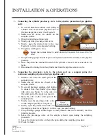
Using an auxiliary pre-charge gas:
When using an auxiliary gas, the pre-charge side of the cylinder should be pressurized
with a regulated gas supply (i.e., nitrogen or helium) and set 50-100 psi above pipeline
operating pressure, not to exceed the maximum allowable pressure of the device.
1.
Make sure all valves on the sample cylinder are closed.
2.
Use small diameter stainless steel tubing to connect the pre-charge valve to the
regulated auxiliary gas supply. (See Figure 3).
3.
Open the valve on the gas supply.
4.
Slowly open the pre-charge inlet valve on the sample cylinder.
5.
Slowly open the product inlet valve on the sample cylinder (see Figure 4) to relieve
any pressure buildup. The piston will begin to move.
6.
The pre-charge gauge should begin to read pressure and will eventually read the
designated pressure.
7.
Once the piston has reached the end of the cylinder, and obtained between 50-100 psi,
close all valves and check for leaks.
8.
Disconnect the tubing from the cylinder and from the pipeline isolation valve.
2.3 I
NSTALLATION
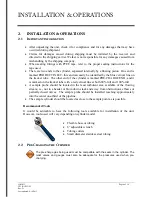
If steps 2.2 Section 1 or 2.2 Section 3 are used to pre-charge, or if the cylinder is being
used for continuous sampling and the pre-charge is not connected to the pipeline, it will
be necessary to install an adjustable, resetting relief valve in order to relieve pre-charge
pressure while continuous sampling.
1.
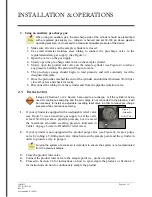
If your cylinder is equipped with an adjustable relief valve
(see Figure 5), use an auxiliary gas supply to set the valve
at least 50-100 psi above pipeline pressure, not to exceed
the maximum allowable working pressure indicated in
Table 1 on page 5 (refer to IO&M for relief valve).
2.
If your cylinder is not equipped with a product purge valve (see Figure 4), create a purge
valve by tubing a T-fitting and valve inline between the sample point and the cylinder in
order to provide a way to purge it.
Purging the system of excess air is important to ensure the system is not contaminated
from the previous sample.
3.
Close the product inlet valve.
4.
Connect the product inlet valve to the sample point (i.e., probe or sampler).
5.
Proceed to Section 2.4 for instructions on how to spot sample the product, or Section 2.5
for instructions on how to continuously sample the product.
Figure 5 -
Adjustable
Relief Valve


