INSTALLATION & OPERATIONS
IOM-013
Page 6 of 18
CP2 & CP5GM
Rev: D
Last updated: 4/14/2011
2.
INSTALLATION
&
OPERATIONS
2.1 I
MPORTANT INFORMATION
After unpacking the unit, check it for compliance and for any damages that may have
occurred during shipment.
Claims for damages caused during shipping must be initiated by the receiver and
directed to the shipping carrier. Welker is not responsible for any damages caused from
mishandling by the shipping company.
When sealing fittings with PTFE tape, refer to the proper sealing instructions for the
tape used.
There are two ends to the cylinder, separated internally by a floating piston. One end is
marked PRODUCT INLET; this end can easily be identified by the blue vertical line on
the tracker tube. The other end of the cylinder is marked PRE-CHARGE END, and it
is marked on the tracker tube with a red vertical line at both 80% full and 100% full.
A sample probe should be located in the least turbulent area available of the flowing
stream; i.e., not in a header or blow-down stack and away from obstructions, elbows or
partially closed valves. The sample probe should be installed reaching approximately
into the center one-third of the pipeline.
The sample cylinder should be located as close to the sample point as is possible.
Recommended Tools
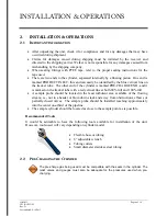
It would be advisable to have the following tools available for installation of the unit.
However, tools used will vary depending on cylinder model.
Flexible hose or tubing
6” adjustable wrench
Tubing
cutters
Small diameter stainless steel tubing
2.2 P
RE
-C
HARGING THE
C
YLINDER
The pre-charge gas being used must be compatible with the seals in the cylinder. The
relief valves and gauges must also be adequate for the pressures used when pre-
charging.


