MAINTENANCE
IOM-013
Page 13 of 18
CP2 & CP5GM
Rev: D
Last updated: 4/14/2011
3.3
D
ISASSEMBLY
(
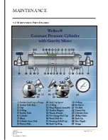
Refer to Diagram on Page 12
)
1.
Make sure the unit is depressurized prior to maintenance.
2.
Remove the two cylinder feet (Part 23).
3.
Remove the six nuts (Part 22) and carefully slide the product end cap (part 1) off the six
tie bolts (Part 21).
4.
Remove the tracker tube clips (Part 3) and tracker tube seats (Part 2).
5.
Remove the tracker tube (Part 5).
6.
When necessary, replace the burst discs (Parts 16 and 17) located on the end caps.
Burst discs should be replaced after 6-10 cylinder fillings or at least once a year. While the
discs do help to maintain the product, they are designed as a safety device to prevent over-
pressurization of the cylinder.
Insert the clear seal.
Insert the rupture disc after the clear seal. The dome should face out.
Torque the bursting relief caps to the proper specification (see Table 2).
1.
Carefully remove the cylinder (Part 6) by sliding it out of the pre-charge end cap (Part 15)
and the six tie bolts (Part 21).
2.
Push the piston (Parts 9, 12, and 14), mixing rod (Part 8), and mixer (Part 7) out of the
cylinder using a stick of wood or PVC.
Be careful not to scratch the surface of the
cylinder or the piston!
3.
Loosen the set screw (Part 20) in the piston assembly. Disconnect the male piston (Part
14) from the ring magnet (Part 12) and female piston (Part 14).
4.
Slide the piston off the mixing rod.
3.4
M
AINTENANCE
I
NSTRUCTIONS
Do not dig into the metal surfaces of the parts when removing O-rings from the O-ring
grooves. Scratching the sealing surface can result in a leak. If necessary, dig into the O-
ring, and replace it during reassembly. If the sealing surface becomes damaged, use a
600-grit wet sandpaper strip to smooth the surface, and then clean it. Check the ball
bearing for any signs of wear or damage. Replace if necessary.
1.
Remove and replace the backups (Parts 25 and Part 10) on the male and female piston,
and remove and replace the O-rings (Parts 4, 11, and 15) in the male and female piston.
(See Figure 8 on next page).
2.
Remove and replace the O-rings (Part 4) in each end cap.
3.
Remove and replace the backups and O-ring (Parts 18 and 19) on the mixing rod.
4.
Wipe down the inside of cylinder and dry carefully (also see Section 3.6).
Table 2


