background image

OPERATING  INSTRUCTIONS  FOR  GAMBIT EQUALIZER EQ1-DYN

TECHNICAL DATA

Daniel Weiss Engineering Ltd., Florastr. 42, CH-8610 Uster 

Page  18 of 27

)

 +41 1 940 20 06    

2

 +41 1 940 22 14  

8

 http://www.weiss.ch 

*

 [email protected]

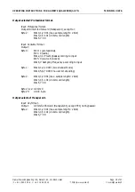
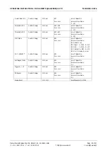
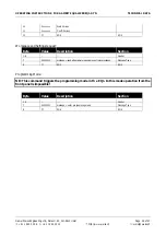
Output selected: Professional format.

Input: Professional format.

Output: All bits fed forward (transparent), except for:

Byte 2:

Bits 0,1,2: 001 (max. sample length= 24bit)

Bits 3,4,5: 101 (24 bit word length)

Bits 6,7: 00

Input: Consumer format.

Output:

Byte 0:

Bit 0: 1 (professional)

Bit 1: 0 (audio)

Bits 2,3,4: Preemphasis according to input

Bit 5: 0 (source fs locked)

Bits 6,7: Sampling Frequency according to input

Byte 1:

Bits 0,1,2,3: 0001 (two channel mode)

Bits 4,5,6,7: 0000 (no user bit encoding)

Byte 2:

Bits 0,1,2: 001 (max. sample length= 24bit)

Bits 3,4,5: 101 (24 bit word length)

Bits 6,7: 00

Bytes 3..12: All bits 0

Byte 23:

CRCC byte

Output selected: Transparent.

Input: Any format.

Output: 

All bits fed forward (transparent), except if EQ not bypassed:

Byte 2:

Bits 0,1,2: 001 (max. sample length= 24bit)

Bits 3,4,5: 101 (24 bit word length)

Bits 6,7: 00
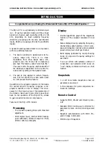
Summary of Contents for EQ1-DYN

Page 1: ...al audio weiss engineering ltd Florastrasse 42 8610 Uster Switzerland 41 1 940 20 06 2 41 1 940 22 14 8 http www weiss ch http www weiss highend com GAMBIT EQ1 DYN OPERATING MANUAL Software Version 0S...

Page 2: ...shots ________________________________________________________________________________ 12 Dither ___________________________________________________________________________________ 14 Display Resoluti...

Page 3: ...NS FOR GAMBIT EQUALIZER EQ1 DYN FRONT PANEL Daniel Weiss Engineering Ltd Florastr 42 CH 8610 Uster Page 3 of 27 41 1 940 20 06 2 41 1 940 22 14 8 http www weiss ch weiss weiss ch FRONT PANEL Graph 1 F...

Page 4: ...t panel of the EQ1 offers several control and display features These can be grouped according to Graph 1 Front Panel Elements Band Parameters Menu Controls Snapshots This manual will explain how to op...

Page 5: ...the bands the overall dynamic frequency response is dis played in real time in the LC display This is nec essary for the proper setup of the parameters of the dynamic band and it gives direct visual...

Page 6: ...annel To reset these values press key B twice Peak Hold The numeric peak value is measured relative to 0dBFS where 0dB equals digital full scale Use this value to set the optimal gain for a specific s...

Page 7: ...r use The number of the last recalled snapshot will be displayed If you change any value after the recall the will change to to symbolize that the workspace is not equal to the displayed snapshot anym...

Page 8: ...active mode see Graph 3 Graph 3 Mode LEDs To activate a band and see its detailed parameter values touch any knob in a band see Graph 1 The active band s parameter values will be shown in the band di...

Page 9: ...de This allows for linear gain adjustment be fore and after a dynamic band Controls See Graph 1 Front Panel Elements CH1 CH2 These two keys patch the band controls to the according channels The band c...

Page 10: ...in instrument within a complex piece of music It is clear from our hearing experiences that most instruments overlap in their frequency ranges so trying to affect one certain instrument by EQ without...

Page 11: ...the top left corner of the frequency re sponse window to indicate that M S mode is ac tive Setup Several possible M S configurations can be acco modated for in the EQ1 This can be achieved with the M...

Page 12: ...preview mode outlined to facilitate finding a certain setting However the audio signal is not affected if the Preview option is marked Once you have found the snapshot press key D to restore it If th...

Page 13: ...ntrol port is activated see chapter Remote Control for setup When dumping to a MIDI sequencer make sure that the sequencer is not sending or receiving data other than the snapshot dump Certain sequenc...

Page 14: ...er is activated Display Resolution The magnitude of the overall frequency response of the EQ1 is drawn on the LC display This im mensely facilitates filter parameter adjustment because it takes one lo...

Page 15: ...ge the remote control channel number press key C adjacent to the remote control field Use the gain data encoder to select a value between 1 and 16 Press the menu key to re turn to the status display T...

Page 16: ...accepts professional or consumer format Channel Status Bits forwarded to AES EBU output see table below Connector XLR female AES EBU Output Sampling Frequencies 44 1 kHz 48 0 kHz 88 2 kHz 96 0 kHz al...

Page 17: ...lected Consumer format Input Consumer format Output All bits fed forward transparent except for Byte 1 Bits 0 6 0000000 category code general Bit 7 1 original Input Professional format Output Byte 0 B...

Page 18: ...00 Input Consumer format Output Byte 0 Bit 0 1 professional Bit 1 0 audio Bits 2 3 4 Preemphasis according to input Bit 5 0 source fs locked Bits 6 7 Sampling Frequency according to input Byte 1 Bits...

Page 19: ...1 940 22 14 8 http www weiss ch weiss weiss ch Power Mains Voltage 110 220 Volts with voltage selector Fuse rating 500 mA slow blow Power Consumption 40VA max Overload Number of consecutive over samp...

Page 20: ...17 0 16 0 15 0 14 0 13 0 12 0 11 5 11 0 10 5 10 0 9 5 9 0 8 5 8 0 7 5 7 0 6 5 6 0 5 5 5 0 4 8 4 5 4 3 4 0 3 8 3 5 3 3 3 0 2 9 2 8 2 7 2 6 2 5 2 4 2 3 2 2 2 1 2 0 1 9 1 8 1 7 1 6 1 5 1 4 1 3 1 2 1 1 1...

Page 21: ...king filters All numbers in dB 0 1 2 3 4 5 6 7 8 9 10 11 12 13 14 15 16 17 18 19 20 21 22 23 24 25 26 27 28 29 30 31 32 33 34 35 36 37 38 39 40 41 42 43 44 45 46 47 48 49 50 51 52 53 54 55 56 57 58 59...

Page 22: ...06 2 41 1 940 22 14 8 http www weiss ch weiss weiss ch Dither Dithering algorithm is implemented using the POW R set of algorithms Graph shows the three algorithms at 44 1kHz and 88 2kHz sampling rat...

Page 23: ...cccc Channel No CH1 Band 1 0vvv vvvv vvvvvvv New Value 0 127 Adjust Q Control Change 1011 cccc 00000001 01 cccc Channel No CH1 Band 1 0vvv vvvv vvvvvvv New Value 0 127 Adjust Frequency Control Change...

Page 24: ...cc Channel No 0vvv vvvv vvvvvvv New Value 0 127 MSC Mode Control Change 1011 cccc 50 cccc Channel No 0vvv vvvv vvvvvvv New Value Bit 0 on off 1 on Bit 1 Input 1 MSC 0 L R Bit 2 EQ 1 MSC 0 L R Bit 3 Ou...

Page 25: ...he supported MIDI system exclusive commands without header Snapshot format for dump A complete dump consists of 128 snapshots Byte Value Description Section 1 6 Header 7 00000001 message Snapshot dump...

Page 26: ...v Coeff Version 12 F7 EOS EOS Workspace and Settings request Byte Value Description Section 1 6 Header 7 00000110 message send all parameters as single controler messages Message Type 8 F7 EOS EOS Pro...

Page 27: ...to MIDI Connector Type D SUB female 9 pin Pinout pin 1 n c pin 2 RS232 output pin 3 RS232 input pin 4 connected to pins 6 8 pin 5 ground pin 6 connected to pins 4 8 pin 7 n c pin 8 connected to pins...

Reviews: