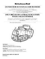
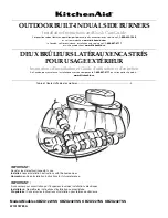
Weishaupt WGL40/1-A ZM, Manual
The Weishaupt WGL40/1-A ZM is a versatile and high-performance combustion system. To ensure seamless operation, it is crucial to have a comprehensive manual at hand. You can easily access and download the free user manual for the WGL40/1-A ZM from manualshive.com, assisting you in maximizing the potential of this exceptional product.
Share
Download


Reviews:
No comments
Related manuals for WGL40/1-A ZM

TC42.NG02DN
Brand: Town & Country Fireplaces Pages: 12

TCWS.38NG04.C
Brand: Town & Country Fireplaces Pages: 16

TC54.NG04C2
Brand: Town & Country Fireplaces Pages: 16

TCWS.38CE2
Brand: Town & Country Fireplaces Pages: 44

LO140 G-.TN Series
Brand: Unigas Pages: 36

GSBSEAR-LP
Brand: Jackson Grills Pages: 9

MO-111
Brand: QookingTable Pages: 5

Grand Turbo BGTSBLP
Brand: Barbeques Galore Pages: 20

TBG 320SLX ME
Brand: baltur Pages: 100
KBZU122T
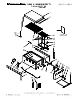
Brand: KitchenAid Pages: 32
KBZU122TSS - 17" Side Burner
Brand: KitchenAid Pages: 48
KBEU121TSS00
Brand: KitchenAid Pages: 2

KBZU242TSS00
Brand: KitchenAid Pages: 2

P250AF
Brand: Wayne Pages: 25

Minicomist 7
Brand: baltur Pages: 38

HP60
Brand: Unigas Pages: 36

EHA
Brand: Wayne Pages: 10

AA-11-04745
Brand: NetZero Pages: 15


