Weir ROTO-JET 2100 Installation, Operation & Maintenance Manual Download Page 31


27 

B.


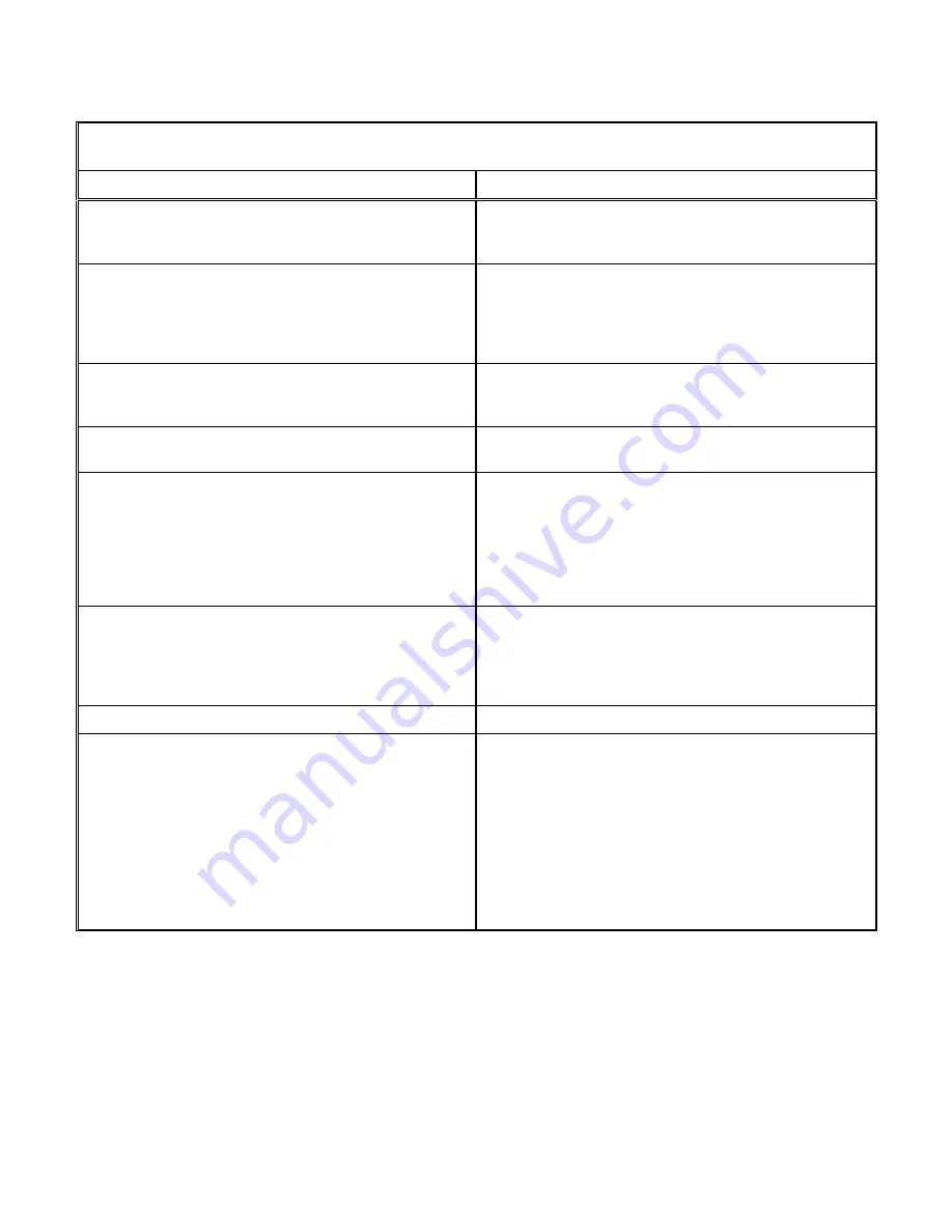
NOT ENOUGH LIQUID DELIVERED AT END DELIVERY POINT 

OR THROUGH FLOW METER 

Possible Causes 

Corrective Action 

1.  Air Leak in Suction Line. 

Suction line can be tested by shutting off or plugging 
inlet and putting line under pressure.  A gauge will 
indicate a leak with a drop of pressure. 

2.  Speed Too Low. 

Slipping drive belts – check belt tension.  Check driver 
sheave and verify correct size for required speed.  
Check whether motor is directly across-the-line and 
receiving full voltage.  Frequency may be incorrect, 
motor may have an open phase. 

3.  Wrong rotation. 

Check motor rotation with required pump rotation.  
Pump rotation is clockwise viewed from manifold end of 
pump. 

4.  Obstruction in Liquid Passages. 

Dismantle pump and inspect passages of pick-up tube, 
rotor cover and manifold.  Remove obstruction. 

5.  Discharge Head Too High. 

Total system head greater than head for which pump 
designed.  Check pipe friction losses.  Larger piping 
may correct condition.  Are valves wide open?  Increase 
pump speed to develop greater differential pressure. 
CAUTION – Brake HP of pump varies as the cube of 
the speed; therefore, any increase in speed means 
considerable increase in power demand. 

6.  Suction Lift Too High. 

If no obstruction at inlet, check pipe friction losses.  
However, static lift may be too great.  Measure with 
mercury column or vacuum gauge while pump 
operates.  If static lift is too high, liquid to be pumped 
must be raised or pump lowered. 

7.  Suction or Discharge Line Partially Plugged. 

Unplug line. 

8.  Inlet Cavitation. 

Insufficient NPSH (Net Positive Suction Heat) available. 
 Available NPSH must always equal or exceed the 
required NPSH of the pump.  Depending on installation: 

A. 

Increase inlet pressure to pump. 

B. 

Reduce inlet pipe friction losses. 

C.  Increase height of suction vessel. 
D.  Pressurize suction vessel. 
E.  Lower the pump. 


Summary of Contents for ROTO-JET 2100

Page 1: ...Installation Operation Maintenance Manual Model RO RG R11 RD11 2100 2200 RJ IOM 03 15 Excellent Engineering Solutions ...

Page 2: ...UCTION 1 B PUMP IDENTIFICATION 2 C RECEIVING INSPECTION 2 D UNLOADING 2 E STORAGE INSTRUCTIONS 3 II INSTALLATION 4 A LOCATION OF PUMP 4 B INSTALLATION ON FOUNDATION 4 C GROUTING 5 D PIPING 6 1 GENERAL 6 2 BYPASS 6 3 FILTRATION 9 4 SEAL DRAIN 9 5 SEAL FLUSH 10 E ALIGNMENT 10 F V BELT DRIVE 12 G ELECTRIC MOTOR DRIVE 13 H GUARDS 13 ...

Page 3: ...RE STARTING 15 C START UP 16 D OPERATING CHECKS 17 E OPERATING CAUTIONS 17 F SHUTDOWN 18 IV MAINTENANCE 19 A GENERAL 19 B MAINTENANCE TIMETABLE 20 C V BELT DRIVE 20 D STRAINER 21 E MECHANICAL SEAL 21 F BEARING LUBRICATION 21 1 OIL LUBRICATED 21 2 GREASE LUBRICATED RG 2100 22 G BEARING SYSTEM 23 H ROTOR AND ROTOR COVER 23 I PICK UP TUBE 23 J OPERATING MAINTENANCE RECORDS 24 ...

Page 4: ...HOOTING 25 A NO LIQUID DELIVERED 25 B NOT ENOUGH LIQUID DELIVERED 26 C NOT ENOUGH PRESSURE 27 D PUMP OVERLOADS DRIVER 28 E PUMP WORKS FOR AWHILE THEN QUITS 28 F PUMP VIBRATION 29 G BEARINGS OVERHEAT OR WEAR RAPIDLY 29 H LIQUID RUNS FROM DRAIN HOLE 30 I NOISE 30 VI PARTS 31 A SPARE PARTS LISTS 31 B ORDERING PARTS 31 C ASSISTANCE 31 ...

Page 5: ...ry service of any mechanical unit however is dependent upon correct application proper installation periodic inspection and careful maintenance For this reason you are urged to read and follow the directions in this manual The exclusive patented Roto Jet Pump has only two basic working parts a rotating case and a stationary pick up tube collector arm within the rotating case The Roto Jet design co...

Page 6: ...OMPANY PROMPTLY Do not remove any tags or shaft protector Instruction sheets on various components as well as the Operation and Maintenance Manual for the pump are included in the shipment DO NOT DISCARD D UNLOADING Care must be taken when unloading pumps WARNING EQUIPMENT LIFTING DEVICES SUCH AS CHAIN LIFTING EYES HOOKS ETC MUST BE APPROVED BY LOCAL STATE OR FEDERAL SAFETY CODES HOISTS AND CRANES...

Page 7: ... parts should be inspected periodically and coated with lubricant or rust preventative IF THE PUMP IS TO BE STORED OR NOT PLACED IN OPERATION MORE THAN TWO WEEKS AFTER RECEIPT 1 Store pump in a clean dry place free from vibration and extremes in temperature 2 Protect all exposed unpainted surfaces from rust 3 On RO ROH R11 and 2200 pumps every two weeks remove the Pedestal Cover and spray the bear...

Page 8: ...as shown on the pump performance curves Whenever possible the pump should be located below reservoir fluid level to facilitate priming B INSTALLATION ON FOUNDATION A properly mounted base on a rigid foundation is essential for a smooth running pump The foundation should minimally be a 4 100 mm thick concrete slab floor or an 8 200 mm thick concrete pad extending two inches larger in width and leng...

Page 9: ...ks around base edge until the base is level Then suction flanges discharged flanges and coupling faces should be checked by means of a level Corrections may be made for flange or coupling level or plumb by shims under the pump or motor ...

Page 10: ...er may be required for suction piping This will depend on flow fluid temperature fluid vapor pressure and losses in elbows valves and strainers Both inlet and discharge piping must be independently supported near the pump and properly aligned so that no pipe strain is transmitted to the pump manifold WARNING SUCH PIPE STRAINS COULD RESULT IN STRUCTURAL FAILURE LEADING TO INJURY The inlet piping sh...

Page 11: ...uld occur a widely fluctuating discharge pressure will be noted If there is any possibility of high pressure remaining on the outlet of the pump after the pump has been shut down as with two or more pumps operating in parallel or when pumping to a high pressure reservoir a check valve must be added to the discharge side of the pump and a pressure relief valve set at 225 psi 15 5 bar or less must b...

Page 12: ...Jet Pump selected MODEL ORIFICE SIZE R11 RD11 S252 3 32 2 387 mm R11 RD11 S338 3 32 2 387 mm R11 RD11 S433 1 8 3 175 mm R11 RD11 D433 5 32 3 962 mm RG RO 2100 2200 S266 3 32 2 387 mm RG RO 2100 2200 S375 3 32 2 387 mm RG RO 2100 2200 S484 1 8 3 175 mm RG RO 2100 2200 D484 1 8 3 175 mm RG RO 2100 2200 S600 1 8 3 175 mm RG RO 2100 2200 D600 5 32 3 962 mm RO D850 5 16 7 930 mm We recommend that 13 mm...

Page 13: ...PEND ON THE PARTICLE SIZE AND HARDNESS CONSULT FACTORY FOR FILTRATION AND SPECIAL PARTS RECOMMENDATIONS IF THIS LEVEL IS EXCEEDED 4 SEAL DRAIN In the event of seal failure the leakage will exit from the seal drain Piping may be connected to the seal drain except the RG 2x2 and piped away from the unit but it should never be plugged If pumping other than water please consult the factory Leakage sho...

Page 14: ...d to optimize bearing life with their respective type drive Warranty will not be extended to any problems or damage due to misapplication If necessary the bearing system can be converted to suit the drive system selected See Disassembly Assembly manual Flexible Coupling Drive Model Suffix A Flexible couplings are not intended to permit permanent misalignment Even slight misalignment will reduce be...

Page 15: ...a piece of string can be used If the sheaves are properly lined up the straightedge or string will touch each sheave at two points and both sheaves at four points simultaneously Rotating each sheave a half revolution will determine whether the sheave is wobbly or the drive shaft is bent Correct any misalignment The sheaves should be mounted as close as possible to the pump and motor bearings With ...

Page 16: ...me side Adjust take up until belts are snug and then tension the drive properly The following tensioning information are general guidelines for equipment supplied by the factory For specific tensioning data consult the factory or belt manufacturer Measure the span distance between centerlines of sheaves The deflection at mid span should be 1 64 per in of span i e for a span of 24 the deflection is...

Page 17: ... smaller motor is used a slow trip overload relay is recommended to prevent tripping during start up The rotor assembly of a Roto Jet pump has a relatively high moment of inertia and requires an extended acceleration period with these motors before operating speed is reached WARNING ALL ELECTRICAL CONNECTIONS AND WIRING ARE TO BE IN COMPLIANCE WITH LOCAL BUILDING AND SAFETY CODES DO NOT OPERATE EQ...

Page 18: ...GPM 105 6 M3 hr 9 GPM 2 0 M3 hr 535 GPM 121 5 M3 hr 2 GPM 5 M3 hr Specific Gravity 2 1 2 0 6 1 2 0 6 1 2 0 6 1 2 0 6 1 2 0 6 Horsepower Direct Connect Belt Drive 400 HP 290 kw 250 HP 186 kw 3 4 400 HP 290 kw 250 HP 186 kw 3 4 400 HP 290 kw 3 4 400 HP 290 kw 250 HP 186 kw 3 4 400 HP 290 kw 250 HP 186 kw 3 4 Fluid Temperature Water Single Seal Single Seal with cooled flush Double Seal with cooled fl...

Page 19: ... GPM 4 GPM 158 GPM 4 GPM 158 GPM 4 GPM Specific Gravity 2 1 2 0 6 1 2 0 6 1 2 0 6 1 2 0 6 Horsepower 75 HP 55 kw 7 75 HP 55 kw 7 75 HP 55 kw 15 HP 11 75 HP 55 kw 15 HP 11 Fluid Temperature Water Single Seal Single Seal with cooled flush Double Seal with cooled flush Other Fluids 180 F 82 C 250 F 121 C Higher of 20 F 7 C or fluid freezing temperature 180 F 82 C 250 F 121 C 275 F 135 C 5 350 F 177 C...

Page 20: ...ush and injection requirements 2 3 GPM at 15 20 1 03 1 4 BAR psig above suction pressure Temperature of fluid dependent on required temperature difference Consult factory 9 Speed limitations by motor size 10 Suction pressure limitations by motor size 11 Minimum motor frame size for the RD11 pump 12 Speed limitations by bearing arrangement and pick up tube selection 13 Speed limitations by bearing ...

Page 21: ...on refer to Disassembly Assembly Manual Section Drawing 2 4 5 Prime pump The Roto Jet pump is not a self priming pump and may be damaged if run dry It must always be filled completely with liquid before starting 5 1 Be sure all valves in the suction line are fully open 5 2 If the pump is installed with a positive head on the suction prime by opening the inlet valve while venting air out of dischar...

Page 22: ...orrectly Bearing temperatures should not exceed 180 F 82 C for ambient pumping temperatures E OPERATING CHECKS 1 Check the pump and piping to assure that there are no leaks 2 Check and record inlet and discharge pressure gauge readings for future reference 3 Check and record voltage amperage per phase and KW if an indicating wattmeter is available 4 Note any unusual noise or vibration F OPERATING ...

Page 23: ...ructions WARNING TO PREVENT PUMP FROM FREEZING DURING COLD WEATHER THE LIQUID IN THE ROTOR ASSEMBLY MUST BE DRAINED FAILURE TO REMOVE THE LIQUID DURING FREEZING TEMPERATURES COULD RESULT IN SEVERE DAMAGE TO THE PUMP 5 For long term pump storage in cold temperatures drain the liquid in the rotor assembly by doing the following 5 1 Remove the NPT pipe plug in the endbell 5 2 Rotate the pump until on...

Page 24: ...aintenance procedure will keep your pump in good working condition and prevent breakdowns A suggested form for recording pump maintenance is provided at the end of this manual One of the best rules to follow in the proper maintenance of your Roto Jet Pump is to keep a record of actual operating hours Then after a predetermined period of operation has elapsed the pump should be given a thorough ins...

Page 25: ...replace parts as necessary As Required Replace seals maximum allowable leakage is 1 pint per hour 0 5 l Replace seals maximum allowable leakage is 1 pint per hour 0 5 l Clean strainer Clean strainer Adjust or replace drive belts B suffix models Adjust or replace drive belts B suffix models Oil incompatibility may cause bearing failure C V BELT DRIVE Drive should be checked for tension and alignmen...

Page 26: ... mechanical seal is a precision product therefore treat it with care In handling do not scratch the face of the seal or mating ring or let it drop and take particular care not to scratch the lapped face that comes in contact with the seal mating ring Cleanliness is of great importance particularly at the seal faces The seal faces wear in with respect to each other and if disturbed it may be possib...

Page 27: ...ttention before starting provided the pump has been stored in a clean dry place prior to its first operation 2 2 Approved Greases Do not use any grease that is not listed unless it is approved by the factory Failure to comply may result in voiding the warranty 2 3 Approved Substitute Greases for SRI No 2 NOTE The pump is lubricated at the factory with Chevron SRI No 2 APPROVED GREASE BASE MATERIAL...

Page 28: ...H ROTOR AND ROTOR COVER To alleviate vibration damage the rotor rotor cover and drive shaft are assembled and balanced at the factory Unless otherwise specified the assembly is balanced for fluid of specific gravity of 1 0 Other applications may require rebalancing of the rotating assembly Excessive material removal due to erosion corrosion or damage may also affect the balance of the pump The rot...

Page 29: ...CE RECORDS ITEM UNITS DESIGNED VALUE ACTUAL VALUE BY 1 Pump Speed RPM 2 Pump Discharge Pressure PSI BAR 3 Flow GPM M3 hr 4 System Pressure PSI BAR 5 Inlet Pressure PSI BAR 6 Fluid Temperature F C DATE MAINTENANCE PERFORMED BY ...

Page 30: ...power demand 5 Suction Lift Too High If no obstruction at inlet check for pipe friction losses However static lift may be too great Measure with mercury column or vacuum gauge while pump operates If static lift is too high liquid to be pumped must be raised or pump lowered 6 Air Leak in Suction Line Suction line can be tested by shutting off or plugging inlet and putting line under pressure A gaug...

Page 31: ...charge Head Too High Total system head greater than head for which pump designed Check pipe friction losses Larger piping may correct condition Are valves wide open Increase pump speed to develop greater differential pressure CAUTION Brake HP of pump varies as the cube of the speed therefore any increase in speed means considerable increase in power demand 6 Suction Lift Too High If no obstruction...

Page 32: ...tion line can be tested by shutting off or plugging inlet and putting line under pressure A gauge will indicate a leak with a drop of pressure 6 Air or Gases in Liquid May be possible to over rate pump to point where it will provide adequate pressure despite condition Better to provide gas separation chamber on suction line near pump 7 Head Lower Than Rating Pumps Too Much Liquid Pump may be opera...

Page 33: ... Causes Corrective Action 1 Incomplete priming Free pump piping and valves of all air If high points in suction line prevent this they need correcting 2 Suction lift too high If no obstruction at inlet check for pipe friction losses However static lift may be too great Measure with mercury column or vacuum gauge while pump operates If static lift is too high liquid to be pumped must be raised or p...

Page 34: ...he foundation must be rigid enough to support the pump auxiliary equipment drive and baseplate and prevent vibration and misalignment during operation 7 Foreign particles in rotor The accumulation of foreign particles in the rotor may create and unbalanced condition Clean pump rotor 8 Erosion of rotor Check pump rotor for evidence of erosion Displacement of metal within rotor could create an unbal...

Page 35: ...ual or exceed the require NPSH of the pump Depending on installation F Increase inlet pressure to pump G Reduce inlet pipe friction losses H Increase height of suction vessel I Pressurize suction vessel Lower the pump 3 Discharge cavitation Decrease flow requirements increase pump discharge pressure 4 Belts slipping Adjust or replace belts 5 Turbulence in discharge piping A Fully open the discharg...

Page 36: ...ded it can be provided if the correct model and serial number is given Many unnecessary errors and delays may be eliminated by observing the following instructions Your parts order should state 1 Model and serial number of pump 2 Part number description and quantity required 3 Your company name address and zip code clearly 4 Specific shipping and billing instructions 5 Date required With this assi...

Page 37: ...m service and technical assistance please contact our factory for the distributor or representative nearest to your project Weir Specialty Pumps 440 West 800 South Salt Lake City UT 84101 P O Box 209 84110 0209 Tel 801 359 8731 Fax 801 530 7828 info weirsp com www weirpowerindustrial com Excellent Engineering Solutions ...

Reviews: