


5.
To configure static IP for the camera, do the following:
1.
Click
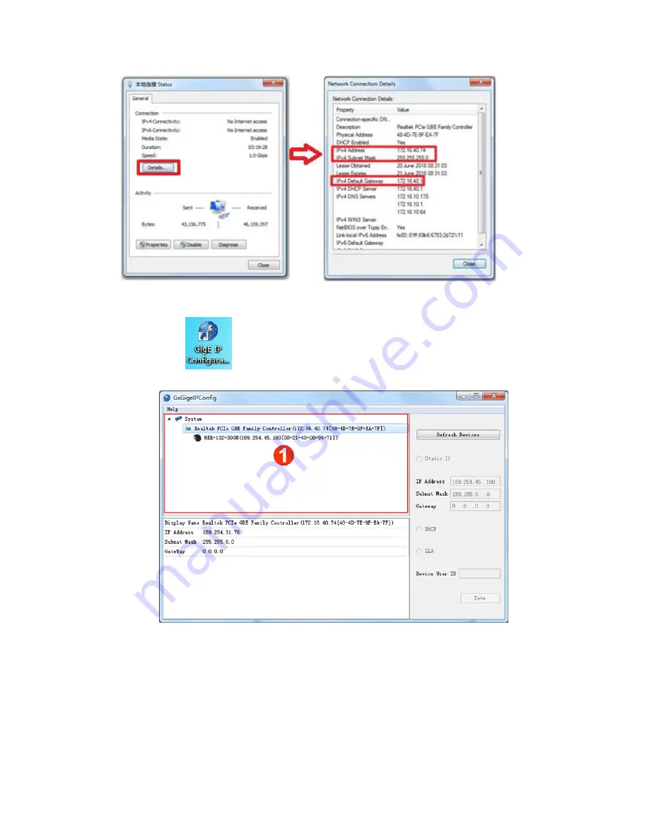
. The dialog box
GxGigeIPConfig
pops up.
2.
Click
Refresh Devices
to refresh the camera list in area ①.
3.
Select the camera in the camera list.
4.
Check
Static IP
and modify the IP address of the camera to the IP
address which is on the same subnet with your computer.
Attention: The IP address of the camera and your computer
must be on the same subnet and cannot conflict with IP
addresses of other terminals. Otherwise, communication
exception occurs.
WEIHONG ELECTRONIC TECHNOLOGY CO., LTD.
- 8 -