background image

Operation and Maintenance Manual of WP13C Series Diesel Engines                                                                                                                              

Weichai Power Pursuit of Excellence 

- 6 - 


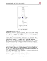
3.2 Internal high pressure connecting 

The high pressure fuel reaches the fuel injector through the fuel inlet joint inside the cylinder head. When 
carrying out proper high pressure sealing of a standard fuel inlet joint, the required minimum pre-pressing 
force is 12kN and maximally 22kN is allowed. If the force is too high, it may lead to overload of fuel inlet 
joint and cause leakage. 
When mounting the fuel inlet joint, please apply lubricating oil on the O-ring and thread pair. Apply 
recommended mineral oil on the threads and shaft shoulder. The oil used must be suitable for material of 
O-ring. If surface lubrication of O-ring and threads is already carried out, oiling is not required. 
Due to lateral sealing force of fuel inlet joint, random mounting will cause improper stress (lateral force 
generated by fuel inlet joint will bend the fuel injector) on the fuel injector, and this is very dangerous. 
Learned from previous practices, tightening in 5 steps is most suitable to minimize the stress distortion of 
fuel injector. 
The recommended 5 steps for tightening the fuel inlet joint are as follows: 
(1) Insert the fuel injector into the cylinder head. Make sure that the fuel injector is properly positioned 
and contact with the seal rings correctly, tighten the clamping bolts of fuel injector by torque of 3Nm; 
(2) Loosen the clamping bolts of fuel injector until the axial force of fuel injector is 0 and make sure that 
the fuel injector is correctly positioned in the cylinder head. 
(3) Pre-tighten the high pressure fuel inlet joint (nut) by the torque of( 15-20)Nm. This force is essential 
for aligning the fuel injector with the fuel hole; 
(4) Tighten the clamping bolts of fuel injector by the torque of 8Nm+90°; 
(5) Tighten the high pressure fuel inlet joint (nut) by the torque of (50-55) Nm. 

Summary of Contents for WP13C450-18

Page 1: ...Operation and Maintenance Manual of WP13C Series Diesel Engines Weichai Power Pursuit of Excellence Operation and Maintenance Manual of WP13C Series Diesel Engines Weichai Power Co Ltd...

Page 2: ...shall not disassemble them Otherwise the warranty will be invalid The supercharger rotor shaft is of precise and high speed rotating part it is prohibited to disassemble or collide it Otherwise the wa...

Page 3: ...stopping if the ambient temperature may be below 0 and there is no antifreeze additive please drain the water in the water tank and the diesel engine 6 Do not operate the diesel engine which is not eq...

Page 4: ...e performance operation test operation and maintenance With the continuous development of production and technology the structure will be further improved and users are reminded of the possible incons...

Page 5: ...cating system 4 3 Fuel system 4 4 Cooling system 7 5 Electrical equipment 8 Chapter IV Maintenance of WP13C series diesel engines 10 1 Maintenance interval of WP13C series diesel engines 10 2 Major wo...

Page 6: ...Operation and Maintenance Manual of WP13C Series Diesel Engines Weichai Power Pursuit of Excellence 1...

Page 7: ...6 2 4 Fuel supply advance angle CA 15 ICXN rated power speed 330kW 1800r min ION overload power speed 363kW 1858 r min Total displacement of piston L 12 54 Minimum stable operating speed r min 810 Idl...

Page 8: ...nd valve mechanism 1 1 Gear train diagram The WP13C series diesel engines adopt the rear mounted gear train figure2 1 in which the gear chamber and the flywheel housing are integrated in order to redu...

Page 9: ...series diesel engine so it is prohibited to use any oil additives Table 2 Lubricating oil grade selection Caution For WP13C mechanical pump series diesel engine it is not allowed to use grade CH and...

Page 10: ...facturing and mounting quality and the fuel quality used influence the performance and reliability of diesel engine The user s fuel tank shall be clean free of rust and corrosion and there shall be no...

Page 11: ...random mounting will cause improper stress lateral force generated by fuel inlet joint will bend the fuel injector on the fuel injector and this is very dangerous Learned from previous practices tight...

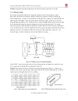
Page 12: ...ling the oil and the diesel engine and ensuring continuous work at the suitable temperature The cooling circulation is divided into long circulation and short circulation When the diesel engine water...

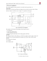
Page 13: ...end See figure 2 9 for generator circuit diagram Pay attention to the following when installing and connecting the geneartor Cool completely Prevent dust splashing and oil Check the generator belt ten...

Page 14: ...iesel engines can be matched with SAE I flywheel housing and gear case for generation When mounting the coaxiality of diesel engine crankshaft and gear case input shaft must be ensured The diesel engi...

Page 15: ...lings must be used for connecting and mount the couplings according to alignment accuracy of different couplings During operation correct the coaxial accuracy regularly to ensure coaxiality of couplin...

Page 16: ...ality find out the causes immediately and troubleshoot timely 3 2 After shutdown of diesel engine check the capacity of fuel coolant and oil and add to the specified level if insufficient 3 3 Drain th...

Page 17: ...r the user shall pay attention to that the oil seal period of diesel engine is 1 year after this period please check and take necessary supplement measures c Rotate the flywheel and spray solvent into...

Page 18: ...ng in period of diesel engine run it with medium load and below c Do not run at idle speed for a long time or it may cause faults such as oil leaking d During normal operation of diesel engine continu...

Page 19: ...ery electrolyte level viscosity and unit voltage If the diesel engine is not used for a long time and the temperature is very low please take down the battery and store it in a warm room f Shutdown Wh...

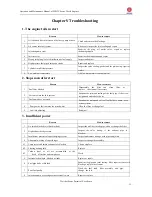
Page 20: ...he joint and sealing of the fuel pipe if the screw is tightened and release the air 3 Fuel pump does not work Examine the piston and valve of feul delivery pump clean or repair them 4 Poor quality fue...

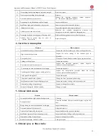
Page 21: ...pipe replace the fuel 4 Leakage with fuel pipe Inspect and repair it 5 Poor atomization of injector nozzle Inspect the injection pressure carbon deposits on the nozzle adjust and repair it 6 Poor tim...

Page 22: ...fails Change 3 Oil pan high level or surplus oil Inspect and drain a proper amount of oil 8 Unstable speed Reason How to remove 1 Poor quality fuel containing water and wax Washing fuel pipe and chan...

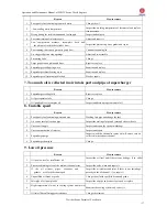
Page 23: ...low level or insufficient oil Inspect the oil level and if there is any leakage if so add oil 4 Oil brand and grade are unqualified Replace by specified oil grade and brand 5 Oil channel blocked Clea...

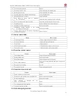
Page 24: ...ails Reason How to remove 1 Undercharged battery Inspect charge and replace the battery 2 Poor wire connection Inspect and tighten the terminal 3 Fuse broken Replace the fuse 4 Electric brush poor con...

Page 25: ...lace the battery Chapter VI List of Wearing Parts of WP13C series diesel engines Part number Name Quantity per unit Remarks 61270040018 Cylinder head gasket 6 61560110210 Turbocharger gasket 1 6126301...

Reviews: