


ENGLISH
15. OVERLOAD PROTECTION:
15.1. Motor Electronic Overload Protection:
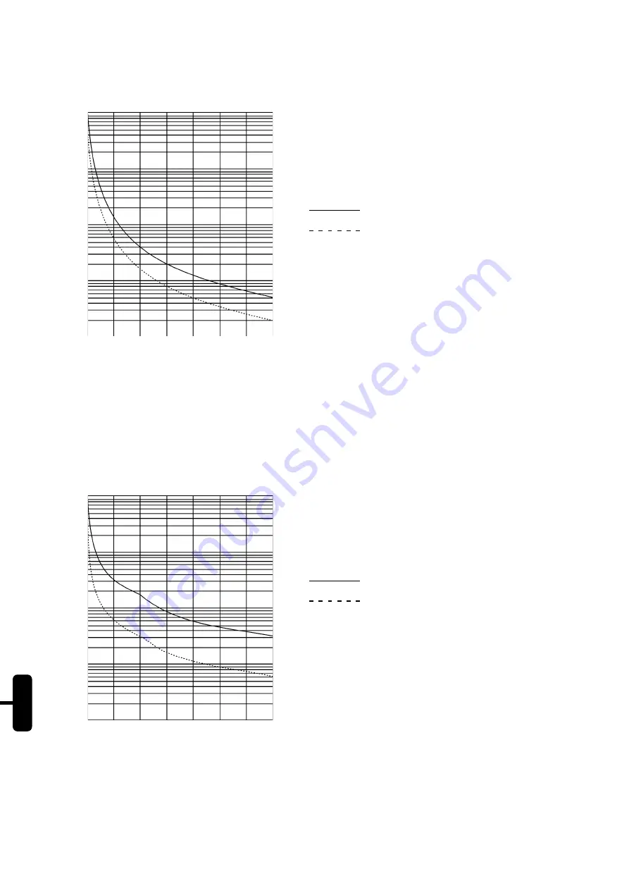
The motor electronic overload protection simulates the motor heating (Thermal Image). This heating simulation uses
as input data the True RMS current. Fig. 15.1 shows the curve of the actuation time with motor under overload
condition. The temperature class of this function is, according to the IEC 947-4-2, Class 10.
Figure 15.1 - Curve of the motor electronic overload protection.
Notes:
1) When SSW-05 Plus electronics (A1 and A2) is without power control supply voltage, the thermal image
is saved internally. When the power supply voltage is re-established again (A1 and A2), the value of the
thermal image returns to the value present before the loss of the power control supply.
2) When the electronic overload protection is disabled via dip-switch, the thermal image is reset;
3) The reset of the electronic overload protection can be set to manual function (man). In this case the
reset must be made via digital input 2 (DI2) or by means of the reset button. If the reset setting has been
set to automatic (auto), the error condition will be reset automatically after the cooling of the equipment.
t(s)
1 + 10
4
1 + 10
3
100
10
1
100
200
300
400
500
600
700
800
% Ief
Cold Condition
Hot Condition
Figure 15.2 - Curve of the thyristor overload.
t(s)
1 + 10
3
100
10
1
0.1
100
200
300
400
500
600
700
800
% In
Cold Condition
Hot Condition
Note:
When the motor is running in full voltage, the cooling of the thyristor overload Thermal Image happens.
This is because of the By-pass of the thyristors.
Buy: www.ValinOnline.com | Phone 844-385-3099 | Email: [email protected]