Installation and Connection
.
26 | ECW500
ATTENTION!
Sensitive equipment, such as PLCs, temperature controllers and thermocouple cables must be
placed at least 25 cm away from the cables between the regulator and the machine.
Table 5.1
Recommended Wiring for Power and Grounding Connection, as per NBR 5410
Input Cables
(P-A / P-B / P-C)
Output Cables
(F+ / F-)
Grounding Wiring
(PE)
4 mm
2
4 mm
2
4 mm
2
(terminal 48)
1,5 mm
2
(terminal 19)
NOTE!
The values of Table 5.1 are only valid in the following conditions:
■
copper cables with PVC 70°C (158 F) insulation;
■
maximum ambient temperature of 50°C (122 F);
■
installation in vertical or horizontal perforated channels;
■
arrangement of the cables in a single layer.
For installation in other conditions, refer to NBR 5410.
NOTE!
The output wiring of the regulator (F+ / F-) must be installed separately from the input power wiring
(P-A/P-B/P-C), as well as from the control and signal wiring.
5.3.2
Protection Fuses
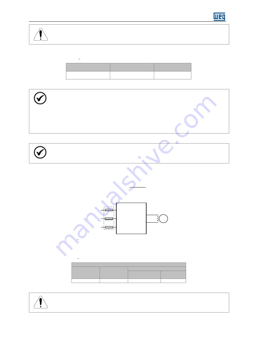
In order to protect the product against short circuit, ultra fast fuses must be used at the regulator input,
dimensioned according to the current and to the maximum of the power I
2
t semiconductors.
Figure 5.4
Configuration of the elements for the protection of the input circuit of the ECW500.
Table 5.2
Recommended Fuses for the Protection of the Input Circuit of ECW500 (AC side)
Fuse
Rated
Current
[A]
Maximum I
2
t
[A
2
s]
WEG Model
Part-number
Code
20
1.200
FNH00-20K-A
10687494
ATTENTION!
Fuses must not be used at the output circuit of ECW500 (F+ / F-).
ECW500
SM
fuses
P-A
P-B
P-C
F-
F+
Summary of Contents for ECW500
Page 2: ......
Page 8: ......
Page 69: ...Modbus RTU Communication ECW500 61 Figure 7 1 Converter USB RS485 ...


