`çãéäÉíÉ=háí==j^k=
`çãéäÉíáçå=çÑ=~ëëÉãÄäó=Öêçìéë
10
111
15
111
15
12
225
75
13
76
12
103
57
619
620
397
631
621
12
602
2
605
13
2
603
606
222
366
109
10
713
14
463
114
624
459
4
R
`~Ä=ëÉÅíáçå=
5.1 Assembling the cab
Use screws 4 to screw the premounted front section onto the roof.
Make sure that on both sides the roof sits absolutely close to the
front section!
With screws 114 and nuts 109 attach the footboards 463 onto the
fenders 605 and 606. Screw on the left fender 606 with screws 10
onto the left side panel 6115, and the right fender 606 onto the right
side panel 603. Side panels with the fenders are now screwed on
as follows: with screws 10 onto the roof, and with screws 2, washer
13 and square nuts 12 onto the front panel along those webs pre-
pared. Now check again the position of the doors and re-adjust them
if necessary.
Should you intend applying a decal it is advisable doing it right now.
5.2 Seat rear panel and battery plate
First pass the switch toggles at the switch panel through the holes
provided in the seat rear panel 222; secure from the front using
four knurled nuts 210 (see therefore illustration 12).
Accordingly to the illustration attach the switch sticker onto the seat
rear panel; the letters indicating the switches do now stand on their
heads. Please see ill. 13b for the assignment of the switches. Now
slide one each square nut 12 into the slits of the four fixing gaps of
the side panels. Then fix the seat rear panel from underneath onto
the side panels using screws 2. Hang both seats 103 onto the seat
rear panel.
Now start mounting the battery carrier plate 225. Turn a nut M3 onto
the door handle 75 and tighten it. Then set on one washer 13 and
one spring washer 14 and insert the handle through the hole pro-
vided for in the battery plate. From the rear slide the door lock 76
over it and screw on one square nut 12. Door handle and door lock
should be fixed that way that they stay right-angled towards. It is ad-
visable using pliers to hold the door lock while securing it with the nut
M3. Finally set the battery plate into place: on the left side panel of
the cab it has to catch the groove provided for, and on the right side
panel insert it underneath that plate with the half-round sparing. By
turning the handle the plate gets locked.
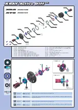
5.3 Assembling the bumper with the lighting
Press the blinker lenses 621 as well as the headlight lenses 624 -the
funnel-formed side showing outwards- into the corresponding open-
ings of the bumper 619. Press one each bulb 713 into the outer clips
for the blinkers, and into the socket 459 for the head lights. Press the
socket, together with the bulbs, from the rear into the recesses of the
reflectors. Glue both reflector foils 631 into the reflectors 620 and
screw then the reflectors onto the bumper using screws 397. With
screws 57 and nuts M3 attach the bumper onto the front panel. Use
caps 366 to cover the recesses in the bumper.
57-e.DOC / K-MAN
Page 4
Cab section ill. 5
Premounted
roof section
Sticker for
switch
Premounted
front section
Qty.
No. Assembly part
2
366 Lens flat, black
2
397 Tapping screw 2.2 x 6.5
2
459 Rubber funnel for
reflector
4
463 Access, fender
1
602 Side panel -lh-, MAN
1
603 Side panel -rh-, MAN
1
605 Fender -lh-, MAN
1
606 Fender -rh-, MAN
1
619 Bumper MAN
2
620 Reflector MAN
2
621 Blinker lens MAN
2
624 Headlight lens, MAN
2
631 Reflector foil MAN
4
713 Bulb 3V
1
--- Decal
1
--- Sticker for switch
Qty.
No. Assembly part
4
--- Nut M3
6
2 Screw M3 x 8
3
4 Screw M3 x 16
4
10 Self-cutting screw M3 x 6
7
12 Square nut M3
3
13 Washer 3.2
1
14 Spring washer 3.2
4
15 Serrated washer 3.2
2
57 Screw M3 x 10
1
75 Door handle
1
76 Door lock
2
103 Seat
4
109 Nut M2
4
111 Self-cutting screw M3 x 8
4
114 Screw M2 x 6
1
222 Seat rear panel
1
225 Battery carrier plate
B-57-3