5 | Standby
4 / 10
2112899A OI Ti22 ProX
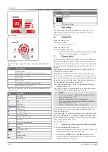
Fig. 2 Design 2
Fig. 3 Design 3
Illustration Fig. 1, Fig. 2 and Fig. 3 show examples of design 1
to 3.
Nr
Description
1
Home screen
(Tap Webasto select crew / parameter menu)
2
Temperature setting
3
ON / OFF
4
Fan display
5
Automatic air handler control display
6
Settings (passenger menu)
The icons on the Home screen provide information about the
system status.
Icon
Function
On / Off
Temperature
Fan
Settings
Crew menu
Notification
Increase values
Decrease values
Automatic fan control
Previous
22
Set-point temperature
Previous
Next
Parameter value
Select
Home screen
Scroll up
Icon
Function
Scroll down
Keypad
Display selection
5
Standby
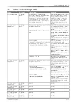
The screen will go to Standby mode after 5 minutes if the
screen remains untouched. Tap anywhere on the screen to
bring up the Home screen.
6
ON/OFF
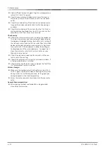
When the screen is off:
l
Tap the screen
– The screen switches on.
When the screen is on:
l
Tap the green / grey field
– The color of the ON/OFF symbol indicates the operating
status of the BlueCool (green = switched on).
7
Operation
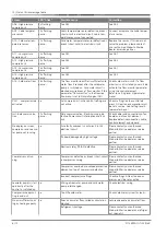
After switching on, the control system starts up the chiller unit
and the connected air handler in steps and then assumes nor-
mal operation. The control element now shows the current tem-
perature where the temperature sensor of the chiller unit is in-
stalled.
Depending on the installation location, this may also be the
temperature of another cabin.
After approx. 20 seconds, the base colour of the control ele-
ment changes to indicate the operating mode (cooling or heat-
ing) in which the chiller unit was started. Blue indicates cooling
mode, red indicates heating mode. The selection depends on:
l
the selected setpoint temperature and
l
the room temperature, which is measured by the cabin
temperature sensor.
The system will go into standby mode when the cabin temper-
ature and the setpoint temperature are the same.
NOTE
The system only cools under the following conditions:
cabin temperature > 15 °C.
Setpoint temperature < cabin temperature.
The system only heats under the following conditions:
cabin temperature < 29 °C.
Setpoint temperature > cabin temperature.
In automatic mode the fan remains set to speed 1 until the cold
water temperature is lower (cooling) or higher (heating) than
the cabin temperature.
In cooling mode, the cold water temperature is significantly be-
low 15 °C and above 40 °C in heating mode. The current cold
water temperature at the outlet of the Ti22 ProX can be reques-
ted in setting level 2 (crew menu).
See Setting level 2.
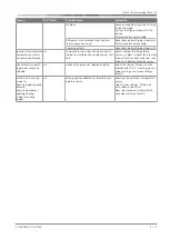
7.1
Selecting the setpoint temperature
To set the required cabin temperature:
1.
Tap the temperature or the icon on the home screen. The
setpoint temperature appears to the right.
2.
Tap the Plus icon or Minus icon to increase or de-
crease the setpoint temperature. The Settings menu closes
automatically after 30 seconds.


