GRANUDOS S5, control unit
Index: 02
Date modified: 11/05/2021
OI No.: BA SW 014-02 Granudos S5-Steuereinheit EN.docx
Page 8 of 29
6
Operation / service of the control unit
6.1
Operation of the display
GRANUDOS S5
The operation modes and faults are displayed directly on the start screen (operation display): see 6.2,
In automatic operation, the current operation mode, the control, the set dosing performance, output for
chlorine or pH dosing and any potential delays or faults are displayed.
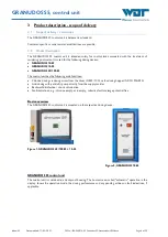
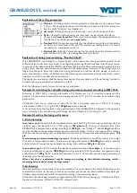
The device is operated by means of 3 operating keys next to the display.
Use the
arrow keys
to navigate up or down or to set numerical values.
Use the
Enter key
to navigate to the selected sub-menu and back.
For an overview of the
menu structure
and abbreviations, see
Chapter 10.1, page
Figure 3, Display with operating panel
Tip - Shortcut!
Back to main menu: Simultaneously touch the two arrow keys for 3
seconds.
Password
There are predefined menu areas that require a password to be entered. The password is automatically
queried in these areas. The password consists of four digits and has a factory default setting of 0123. It
protects defined menu areas against unauthorised access. We recommend that you change this password and
enter the new password in the operation data sheet.
6.2
Start screen (operation display)
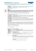
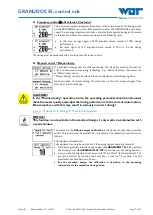
After activating the device, you will see the start screen (also called operation display).
01.
Operation modes line
02.
Input signal external chlorine control active
03.
Input signal external pH control active
04.
Status line / fault indication
05.
Set chlorine dosing performance
06.
Set acid dosing performance
07.
Chlorine dosing active
08.
pH dosing active – Example, cannot be active at
the same time as chlorine
The operation modes line (01) can show the following displays:
Automatic, Manual dosing, GRD OFF, Auto Dos OFF, Start Delay b-pump, filter disinfection (shock
chlorination), CCT OFF
The status line (04) displays general notices and faults:
e.g., start-routine, dos delay XX sec., alarm fuse F2 - F14 as well as additional alarms and faults.
Depending on the operation state, the display shows different views. The following illustrates and describes
the main display views.
Figure 4, Start screen - Explanation


