www.wdmpumps.com
34
PI Operation Manual
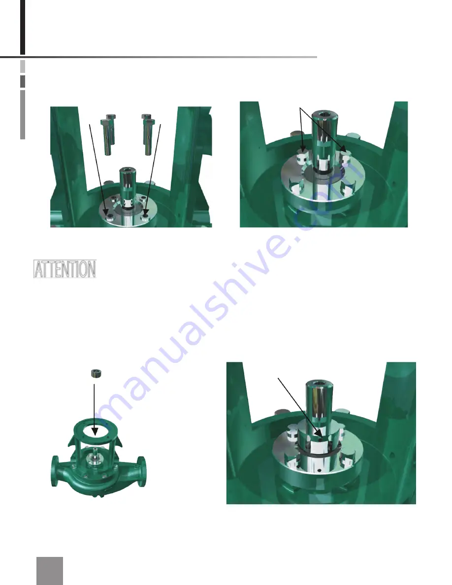
Figure 6.17 Fastening the corresponding screws on the seal gland.
17.
Fasten the corresponding screws on the seal gland.
The NPT hole in the mechanical seal head should be aligned at 90° from the
suction and discharge flanges, that is, perpendicular to the suction and discharge flanges, pointing
towards either side of the pump. This will simplify the connection of the flushing line to the mechan
-
ical seal head.
18.
Place the rotating part of the mechanical seal. Do not tighten the setscrews.
Figure 6.18 Placing the rotating part of the mechanical seal.


