© Copyright
2008-03-20 V0 Rev.01.0
- 9 -
WT004139
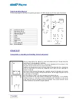
To access internal components for installation and ordinary maintenance, use
the proper key supplied with the dispenser to open lower front panels and/or the
head box.
Installation
Before installing the dispenser, it is necessary to ensure that installation is carried out exclusively by qualified
technicians that are fully knowledgeable about both installation procedures as well as about prevailing
applicable regulations.
All equipment must be installed in compliance with the requirements of the applicable regulations.
In many countries there are norms on safety distance that must be carefully followed. It is necessary to
ensure that these norms are respected, starting from the planning project of the system.
In Italy, the connection of the dispenser to the gas adduction line must take place through an excess flow
valve.
Dresser cannot be held responsible for any damages to persons and/or things deriving
from an improper installation of the dispenser.
When installing, it is necessary to pay particular attention to the following aspects.
Electrical system and safety
Install an emergency stopping system (normally composed of an emergency button and one or more safety
switches) that is capable of interrupt the flow to the equipment in case of operating problems. The emergency
stopping system, not included with the dispenser, must comply with national regulations (for example EN
60204-1). The safety device must be placed in the gas station in order that it is easily accessible to
attendants. Following an emergency stop, the emergency button must be reset before returning back power
to the station.
Returning power must not cause an automatically start of the fuelling.
Ensure that all station attendants fully know where the emergency system is located and how it works.
To install the CNG dispenser, perform the following operations:
•
open front panels;
•
place and fasten the dispenser on the base;
•
make hydraulic connections and check the fastening on the dispenser’s connections;
•
connect electrical wiring, checking electrical values;
•
power the dispenser;
•
open the gas inlet valve;
•
open the air/instrument valve (6
/
8 bar);
•
close front panels;
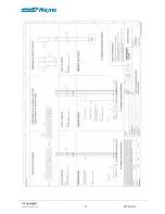
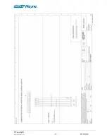
In order to properly make hydraulic and electrical connections, always refer to the diagrams supplied by
Dresser.
During transportation the dispenser’s hydraulic connections may loosen. Check whether all
the dispenser’s connections are tight. Always verify that the dispenser or, more generally, the
whole system has no gas leaks.
Summary of Contents for GLOBAL VISTA CNG
Page 1: ...EN WT004139 2008 03 20 V0 Rev 01 0 Global Vista CNG Instruction Manual ...
Page 10: ... Copyright 2008 03 20 V0 Rev 01 0 10 WT004139 ...
Page 11: ... Copyright 2008 03 20 V0 Rev 01 0 11 WT004139 ...
Page 12: ... Copyright 2008 03 20 V0 Rev 01 0 12 WT004139 ...
Page 13: ... Copyright 2008 03 20 V0 Rev 01 0 13 WT004139 ...
Page 14: ... Copyright 2008 03 20 V0 Rev 01 0 14 WT004139 ...
Page 15: ... Copyright 2008 03 20 V0 Rev 01 0 15 WT004139 ...
Page 25: ... Copyright 2008 03 20 V0 Rev 01 0 25 WT004139 DECLARATION OF CONFORMITY ...


