background image

1

Z-Wave

®


Enabled

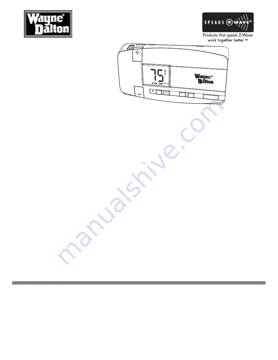
Thermostat

User Manual

For Model WDTC-20

Manage and automate your home’s 

climate to maximize energy 

conservation and comfort

Thank you for purchasing the Z-Wave

®


Enabled Thermostat.  It was designed to give you many years 

of reliable service and easy to use climate control when operated manually or by remote control in a 
Z-Wave

® 

network.  Z-Wave

®

 products by Wayne-Dalton allow you to manage and control your home by 

remote control for convenience, comfort, safety and energy conservation.  Your Z-Wave

®


Thermostat 

is a great addition to your Z-Wave

® 

network and can maximize energy conservation and comfort while 

minimizing the effort required to maintain the appropriate temperature in your home whether you are 
at home or away.  In addition to thermostats, indoor and outdoor lighting, security systems, garage door 
openers and window shades are just a few of the items you can easily control with additional Z-Wave

®


certified products.
Your new Z-Wave

®


Enabled Thermostat is compatible with the complete range of Wayne-Dalton

 Z-Wave

®

 certified controllers.   Your Z-Wave

®


Enabled Thermostat will also work with Z-Wave

®


certified 

controllers from other manufacturers and brands.  Please consult the user manual and your controller 
supplier for more details.

Home Control Basics

Z-Wave

®

 certified products will allow you to easily control multiple devices in a home with the push of a 

button in what is known as a “scene”.  Turning on your home’s interior lights and activating the set-back 
on your thermostat from your in-vehicle remote as you come home is an example of a scene.  Dimming 
the lights and automatically closing your curtains to watch TV with a single push of a button is another 
example of a scene.

Visit www.wayne-dalton.com/access for more ideas on how to create, set-up and use scenes for safety, 
security, comfort and convenience.

IMporTanT noTICE!

Read the enclosed instructions carefully before installing your new Z-Wave

®


Enabled Thermostat. Pay 

close attention to all warnings and notes and carefully follow the installation steps in the order they are 
presented to save time and minimize the risk of damaging the thermostat or the system it controls.

 This manual should be retained for future reference.

AUTO

ON

FAN

HEAT

COOL

SAVE

ENERGY

NORMAL

RESET

COOL

Summary of Contents for WDTC-20

Page 1: ...Z Wave certified controllers Your Z Wave Enabled Thermostat will also work with Z Wave certified controllers from other manufacturers and brands Please consult the user manual and your controller sup...

Page 2: ...mper Reference Guide 11 Wiring Diagrams and Jumper Configurations 12 17 Control Unit Installation 18 Installation Verification 19 Degrees C and F 20 Temperature Offset 20 General Operating Information...

Page 3: ...can control the system Node Single Z Wave endpoint controller or module on a network Primary Controller The first controller used to set up your modules and network NOTE Only the Primary Controller c...

Page 4: ...ate the Home Scene to return the thermostat to your normal setting To begin using Z Wave Home Control technology it is helpful to understand that each Z Wave module including the Z Wave Enabled Thermo...

Page 5: ...ily control with additional Z Wave certified products Your new Z Wave Enabled Thermostat is compatible with the complete range of Wayne Dalton Z Wave certified controllers Furthermore other Z Wave con...

Page 6: ...cate where air circulation is poor such as in a corner or an alcove or behind an open door Do not install the thermostat unit until all construction work and painting has been completed This thermosta...

Page 7: ...ing them around a pencil as shown will keep them from falling 5 Loosen all screws on the existing thermostat and its mounting plate and remove it from the wall Be careful not to disturb wiring labels...

Page 8: ...le positions with a pencil or mount directly to the wall with the two screws provided If mounting the base to sheetrock or if using the existing mounting holes use the plastic anchors provided Drill a...

Page 9: ...s reference chart on page 13 for your exact application as your guide Fan wires out as illustrated in the wiring diagrams with the Z Wave enabled thermostat mounting base positioned below the wall ope...

Page 10: ...occur Power for Cooling system Fan control relay 3rd wire for 3 wire zoned hot water heating systems Heat Pump Systems Common power or hot wire from secondary side of heating system transformer Note...

Page 11: ...rresponds to the bubble number above JP5 Fan Control a NO FAN No fan control even with switch on front of thermostat RARE No jumper b ELECT Fan is controlled from thermostat Jumper on top 4 pins c GAS...

Page 12: ...OM FURNACE C W RH 2 Wire Heat C Wire C W rH FROM FURNACE C W RH Y G 4 Wire Heat Cool C Wire C W rH Y G 5 Wire Heat Cool C Wire C W rH Y G rC FROM FURNACE C W RH Y G RC FROM FURNACE C G RH Y B O or 4 W...

Page 13: ...4 VAC power to power thermostat Do not connect and wrap exposed end with insulating electrical tape Emergency heat is supported by placing jumper 2 in the Aux position Do not connect and wrap exposed...

Page 14: ...o continue your installation JP5 OR B C RH W STEP C On the Control Unit PCB install jumpers as shown See the jumper reference guide on page 11 for jumper number designations Black indicates position o...

Page 15: ...et jumper JP5 in position A for Gas or Oil Heat set jumperJP5 in position B O W2 C B G A RH RC W Y STEP B Connect your wires to the corresponding terminals on the thermostat base Wrap wire around term...

Page 16: ...do not install or remove jumper on jumper JP2 for Electric Auxiliary Heat set jumper JP2 in position B STEP B Connect your wires to the corresponding terminals on the thermostat base Wrap wire around...

Page 17: ...to continue your installation Your Labeled Wires Y RH STEP C On the Control Unit PCB install jumpers as shown See the jumper reference guide on page 18 for jumper number designations Black indicates...

Page 18: ...the OFF state 2 Press and release the RESET button on the front of the control unit to initialize your jumper settings If jumper settings are changed you must press the RESET button Low Battery Icon L...

Page 19: ...from your system D Press and release the HEAT button to shut off the heat 4 Check Air Conditioning NOTE Wait 5 minutes after doing the Heat Check before proceeding A Press and release the COOL button...

Page 20: ...o the OFF position NOTE If using this feature Temperature Offset must be adjusted each time the thermostat is RESET or batteries are removed Example Display shows 2 degree Offset factor JP1 ON OFF JP1...

Page 21: ...to be replaced Z Wave icon If radio waves are present and flashing it indicates it is a node on a Z Wave network If waves are not present then the thermostat is not a node on any Z Wave network ROOM...

Page 22: ...yed press the HEAT button The display will then not show either HEAT or COOL and will display the current room temperature only 3 Press and release the desired operation mode either NORMAL or SAVE ENE...

Page 23: ...ing the word COOL press the COOL button to turn the unit off If the display is showing the word HEAT press the HEAT button to turn the unit off Programming NORMAL HEAT target temperature 2 Press and r...

Page 24: ...y the actual ROOM TEMP Programming NORMAL COOL target temperature 7 Place your thermostat into COOL mode If the display is showing the word HEAT press the COOL button to change to COOL mode The LCD wi...

Page 25: ...the temperature up button symbol or temperature down button symbol until the desired target temperature is reached Wait 5 seconds and the unit will exit target temperature programming mode and remain...

Page 26: ...ng the thermostat to Scenes or Groups or deleting the thermostat as a node use the BIND button to activate the Z Wave signal OPERATION See your specific controller s User Manual for detailed instructi...

Page 27: ...t any thermostat device class functions and also does not support basic ON OFF commands used by lighting switches then a special compatibility feature in your Wayne Dalton Z Wave enabled thermostat is...

Page 28: ...only to Wayne Dalton s WDUSB 10R Z Wave USB Adapter and ThinkEssentials software 1 Open ThinkEssentials to the HOME tab and then ensure the DESIGN TAB is active by pressing it with your mouse 2 Press...

Page 29: ...lton web site www wayne dalton com for updates to your ThinkEssentials software Future updates may include additional thermostat functionality REMOVING THERMOSTAT FROM THINKESSENTIALS 1 Press the REMO...

Page 30: ...only Do not plug the Wireless Gateway into AC power to program 1 On the Wayne Dalton Z Wave Enabled Thermostat press either the HEAT or COOL mode then the NORMAL mode button The thermostat must be in...

Page 31: ...he Wireless Gateway is now complete OPERATING THERMOSTAT 1 Place the thermostat in either the HEAT or COOL mode by manually pressing the appropriate button 2 Press the controller SCENE button you prog...

Page 32: ...to be added to the network correctly 2 Press and release the INCLUDE button on your HA 09WD Remote Control The green LED will flash indicating that the controller is ready to add modules to the syste...

Page 33: ...to the Controller is now complete OPERATING THERMOSTAT 1 Place the thermostat in either the HEAT or COOL mode by manually pressing the appropriate button 2 Press the controller SCENE button ON for NOR...

Page 34: ...apparatus meets all requirements of the Canadian Interference Causing Equipment Regulations Operation is subject to the following two conditions 1 this device may not cause harmful interference and 2...

Reviews: