background image

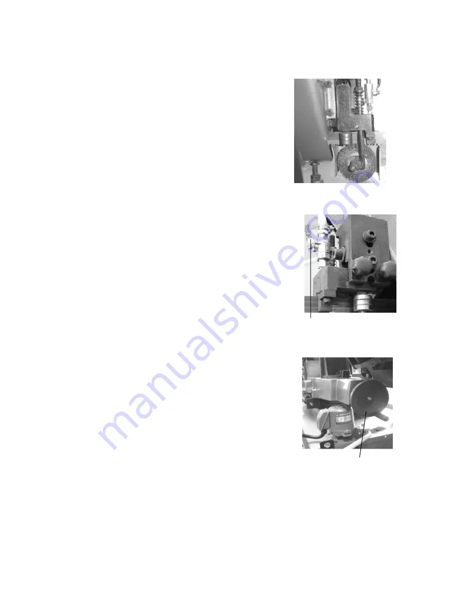
9-8.CLEARING THE CUTTTNG CHIP 

Please use steel brush to clear the chip on the blade teeth (fig 11)


Fig.11 

9-9.BLADE AND COOLING SYSTEM


The use of proper cutting fluid is essential to obtain 

maximum efficiency from a band saw blade. The main cause 

of tooth failure is excessive heat build-up. This is the reason 

that cutting fluid is necessary for long blade life and high 

cutting rates. cutting area and blade wheels should be kept 

clean at all time. 


A          Fig.12       

The rate of coolant flow is controlled by the stop valve lever 

(A) (fig 12), which directs the coolant onto the blade. 

The lever (A) is shown in the off position. 


9-10.OPERATING AND ADJUSTING VISE 


The work-piece is placed between the vise jaws with the 

amount to be cut-off extending out past the blade. Your 

machine is equipped with a "quick action" Vise jaw which 

allows you to instantly position the moveable vise jaw B 

(fig, 14).                                                                                       


Fig.13


Simply turn hand-wheel A


counterclockwise 1/2 turn and move the vise 

jaw s to the desired   


position. Then tighten the vise jaw B against the   

work-piece by turning hand-wheel clockwise.


15

Summary of Contents for 250S

Page 1: ...METAL CUTTING BAND SAW MACHINE MODEL 250S INSTRUCTION MANUAL 250S 060505 R2...

Page 2: ...al are Lead from lead based paints Crystalline silica from bricks cement and other masonry products Arsenic and chromium from chemically treated lumber Your risk from these exposures varies depending...

Page 3: ...6 Minimum Room Space For Machine Operation 8 7 Make Proper Tooth Selection 9 8 BI Metal Speeds And Feeds 10 9 Use Of Main Machine Parts 12 10 Maintaining 19 11 Trouble shooting 19 12 Circuit Diagram...

Page 4: ...1 Overall Aspect Vice Angle Sale Base Motor Cover Change Speed Wheel Tooth selection Control Panel Body Frame 2...

Page 5: ...d 2 SAFETY RULES FOR ALL TOOLS A USER 1 WEAR PROPER APPAREL No loose clothing gloves rings bracelets or other jewelry to get caught in moving parts Non slip footwear is recommended Wear protective hai...

Page 6: ...ch is in OFF position before plugging in power cord 8 DIRECTIONOF FEED Feed work into a blade or cutter against the direction of rotation of the blade or cutter only 9 ADJUST AND POSITION the blade gu...

Page 7: ...e servicing and when changing accessories such as blades bits cutters etc 4 MAKE SURE that blade tension and blade tacking are properly adjusted 5 RE CHECK blade tension after initial cut with a new b...

Page 8: ...ch 76x458mm 3 x18 mm inch 254mm 10 45 mm inch 254x280mm 10 x11 mm inch 204mm 8 Cutting Capacity 60 mm inch 127x204mm 5 x8 4 FEARTURES 1 This machine is useful for cutting normal steel steel pipe and p...

Page 9: ...jack Transportation Recommendation 1 Tighten all locks before operation 2 Always keep proper footing balance while moving this machine and only use a heavy duty of fiber belt to lift the machine as p...

Page 10: ...rn off the power before wiring be sure machine is in proper grounding Overload circuit breaker is recommended for safety B Fig A wiring 6 Keep machine always out from sun dust wet raining area 5 4 CLE...

Page 11: ...ring marked with the square shape which aligns with the width of cut EXAMPLE 6 150mm square use a 2 3 Vari Tooth Round Solids Symbol Locate the diameter of your work piece on the chart Select the too...

Page 12: ...4mm material l0 l4 Vari Tooth 12 When cutting 3 4 19 mm material 6 10 Vari Tooth 10 When cutting 1 1 4 32 mm material 5 8 Vari Tooth 5 When cutting 2 1 2 64 mm material 4 6 Vari Tooth Decrease Band Sp...

Page 13: ...20 189 58 430 149 46 410 502 140 43 414 115 35 431 95 29 440C 80 24 304 324 120 36 304L 115 35 347 110 33 316 316L 100 30 Stainless Steel 416 189 58 TELLTALE CHIPS Chips are the best indicators of cor...

Page 14: ...NG MACHINE A B C D Fig 3 K L M A Fig 4 1 Light D will be on when power is connected Open hydraulic valve F when in operation 2 Start the motor by pushing the start button C Turn A 0 close 1 open to op...

Page 15: ...e A fig 7 clockwise A pointer and tension scale B is located underneath the wheel The scale is graduated to indicate blade tension of 20 000 30 000 and 35 000 pounds per square inch psi For carbon bla...

Page 16: ...ove E the guide block D up or down until it lightly touches the back of the blade 2 The saw blade F should also ride between and lightly touch the two blade guide roller bearings E and B fig 9 Fig 9 C...

Page 17: ...at all time A Fig 12 A The rate of coolant flow is controlled by the stop valve lever A fig 12 which directs the coolant onto the blade The lever A is shown in the off position 9 10 OPERATING AND ADJU...

Page 18: ...any work pieces distance set rod can he used to set a fix cutting length Proceed as follows 1 Let the top of the work piece touch the distance set rod 2 Tighten vise jaw the fix the work piece and get...

Page 19: ...ance bearings 10 Make sure that the saw teeth show to the right direction The saw teeth must show to the driving motor 11 Retighten the saw blade 12 If required readjust the saw blade guidance 13 Clos...

Page 20: ...SW061 Fig 19 A To change the gear oil proceed as follows 1 Run the machine for 10 minutes to warm up the gearbox 2 Disconnect the machine from the power source 3 Raise the saw arm to its maximum posi...

Page 21: ...nce a Check if the fixed portion has been loose b Lubricate bearing worm and worm shaft to avoid the wearing 4 Yearly Maintenance a Adjust table to horizontal position for maintenance of accuracy b Ch...

Page 22: ...speed 3 Decrease spring tension on side of saw 4 Reduce speed increase feed pressure 5 Increase feed pressure by reducing spring tension 6 Replace with a new blade and adjust blade tension 7 Tighten...

Page 23: ...se 8 Blade truck too far away from wheel flanges 1 Reduce pressure by increasing spring tension on side of saw 2 Adjust guide bearing the clearance can not greater than 0 001 3 Increase blade tension...

Page 24: ...12 CIRCUIT DIAGRAM 22...

Page 25: ...OP 23...

Page 26: ...24...

Page 27: ...25...

Page 28: ...26...

Page 29: ...27...

Page 30: ...28...

Page 31: ...29...

Page 32: ...30...

Page 33: ...8 HW004 Washer M6 4 9 103105A Fixed Plate 1 10 HW005 Washer M8 2 11 HS046 Hex Head Screw M8x20L 1 12 HB803 Nut M8 2 14 MB13103R Cooling Pump 1 8HP 60HZ 220V 110V 1 1 14 MB13304R Cooling Pump 1 8HP 50...

Page 34: ...42 Hex Socket Head Screw M8x20L 2 104 HS422 Hex Socker Headless Screw M6x10L 1 105 105015 Cylinder Assembly 1 106 HS422 Hex Socker Headless Screw M6x10L 1 107 103060 Cylinder Upper Support 1 108 10307...

Page 35: ...p Cover 1 141 HS260 Hex Socket Head Screw M10x30L 4 142 HW106 Spring Washer M10 4 143 HW006 Washer M10 4 144 105014 Rear Pivot Bracket 1 145 HB109 Grease Nipple PT1 8 2 146 HS422 Hex Socker Headless S...

Page 36: ...101037A 2 Way Limit Block 1 208 HH001 Rivet 2x5L 2 209 105210 Scale 1 211 HS260 Hex Socket Head Screw M10x30L 4 212 101081A Fix Block 1 213 HW009 Bushing 19x 11x5t 2 214 101113 Knob M10x40L 2 215 105...

Page 37: ...Bracket 1 245 HN006 Hex Nut M10 1 246 HS060 Hex Head Screw M10x30L 1 247 101078 Distance Set Rod 1 250 HS432 Hex Socker Headless Screw M8x20L 2 251 101107 Base Support 2 252 HS241 Hex Socket Head Scr...

Page 38: ...Block PT1 4 x1 2 1 427 4 103125 5 Hose Clamp 19 1 427 5 103127 5 Net Tube ID1 2 x2 8tx320cm 1 427 6 105173 3 Way Valve 1 427 7 103127 2 Micro Control Block PT1 4 x1 4 1 427 8 HS232 Hex Socket Head Scr...

Page 39: ...1 1 479 105076 Shaft 1 480 HS266 Hex Socket Head Screw M10x60L 1 481 HN007 Hex Nut M12 2 482 105075 Shaft 1 482 1 HN006 Hex Nut M10 1 483 191404 Bushing 1 484 103111 Shaft 1 485 HP033 Pin 6x30L 2 486...

Page 40: ...andle Body 1 520 CA51204 Bearing 51204 1 521 103251 Anchor Block 1 550S 103028AS Eccentric Shaft Assembly 2 550 1 HSC01 C Retainer Ring S10 2 550 2 CA609ZZ Bearing 609ZZ 6 550 3 103028A Eccentric Shaf...

Page 41: ...M6x10L 2 571 HS243 Hex Socket Head Screw M8x25L 4 572 HW005 Washer M8 4 573 HW006 Washer M10 2 574 HS262 Hex Socket Head Screw M10x40L 2 575 1965015 Blade Adjustable Knob 1 576 HW006 Washer M10 1 577...

Page 42: ...209 Tooth Selection Paster 1 701 HS241 Hex Socket Head Screw M8x15L 4 702 1965052 Knob 2 703 103127 Hex Socket Head Screw M6x10L 8 704 105018B1 Blade Back Cover 1 705 HW005 Washer M8 4 706 HN005 Hex N...

Page 43: ...MANUFACTURER ADDRESS SERIAL No PLEASE WRITE DOWN THE SERIAL NO ON THIS BLOCK FROM THE NAME PLATE AFTER YOU RECEIVE THIS MACHINE...

Reviews: