SmartSensor 105 User Guide – Wavetronix LLC
9/20/07
- -
14
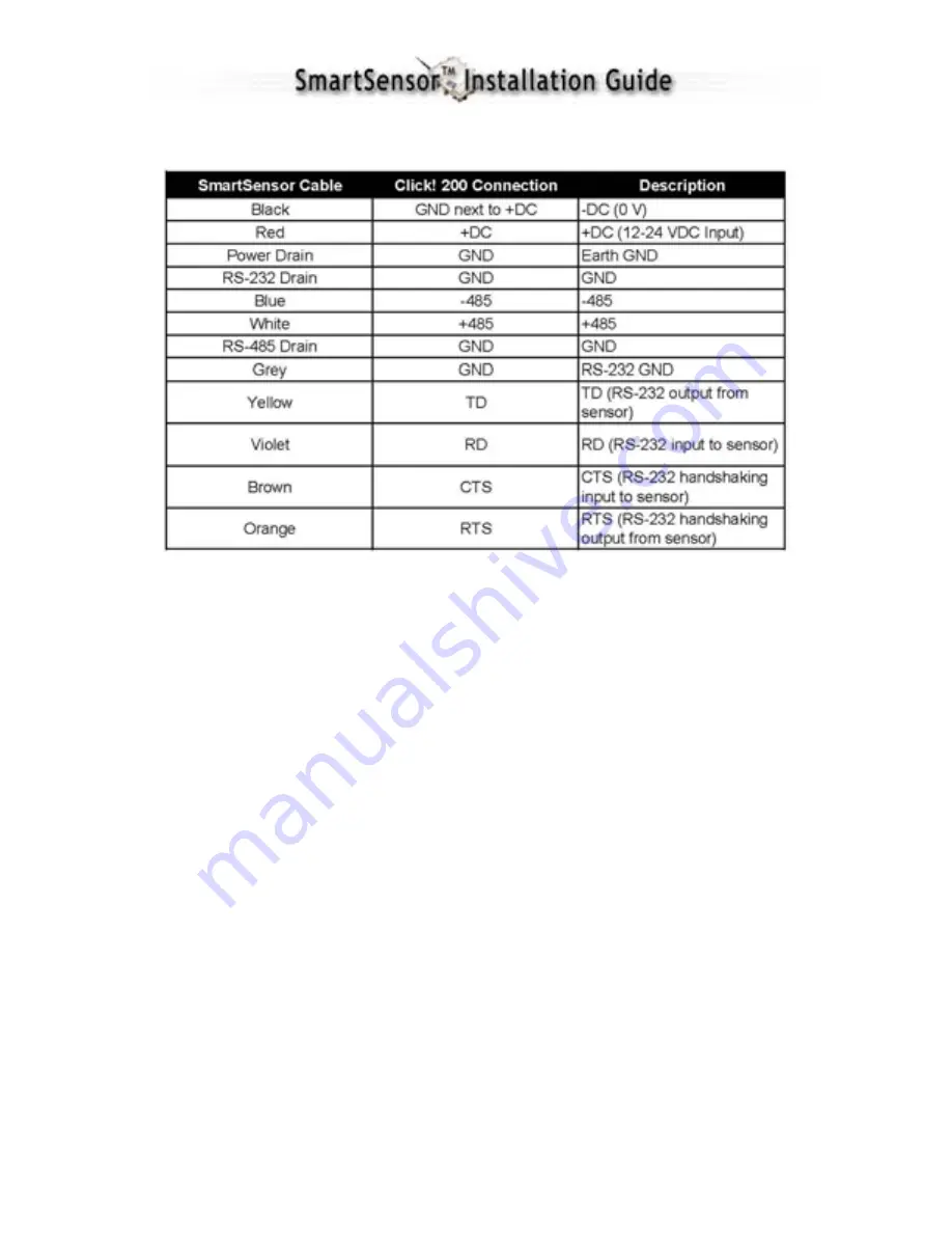
Wire the SmartSensor cable to the Click! 200 according to Table 2:
Table 2 – Click! 200 Connections
NOTE
: See Appendix F for a description of how to wire the Click! 200 using the old
SmartSensor cable as well as for a cable connector pin-out diagram.
7. Configuring SmartSensor with SmartSensor Manager™
After the SmartSensor is installed, it must be configured to the roadway for proper
operation. The SmartSensor Manager software is used to perform this configuration.
Automatic Configuration
1. Connect SmartSensor to a Personal Computer.
SmartSensor can be connected to a
personal computer for on-site configuration; it can also be remotely configured via
wired or wireless modems and Ethernet. These connection options are described in
detail in the SmartSensor Manager manual.
For on
-
site configuration, connect a 9-pin (DB9) null-modem serial cable from the
RS-232 connector on the Click! 200 to the standard RS-232 serial port on your PC.
Wiring diagrams which illustrate connections to a personal computer or to a modem
can be found in Appendix C of this document.
2. Launch SmartSensor Manager by clicking on the shortcut that was placed on your
Windows desktop.
3. When prompted, connect to the SmartSensor you are configuring by the appropriate
method: Serial Connection (if connected via RS-232 or RS-485); Modem (requires
Summary of Contents for SMARTSENSOR 105
Page 7: ...SmartSensor 105 User Guide Wavetronix LLC 9 20 07 7 Table 1 Mounting Height Guidelines...
Page 12: ...SmartSensor 105 User Guide Wavetronix LLC 9 20 07 12 Figure 6 Long Distance Cable Run...
Page 34: ...SmartSensor 105 User Guide Wavetronix LLC 9 20 07 34 Table 7 Belden 9331 Old Cable Conversions...


